uX MANUAL
6
118151-001 REV A
Chapter 3
Operating Instructions
3.1 Operation
WARNING
THIS EQUIPMENT GENERATES
DANGEROUS VOLTAGES THAT MAY BE
FATAL. PROPER GROUNDING OF ALL HIGH
VOLTAGE EQUIPMENT IS ESSENTIAL.
WARNUNG
DIESES GERÄT ERZEUGT
LEBENSGEFÄHRLICHE HOCHSPANNUNG.
ALLE HOCHSPANNUNGSGERÄTE MÜSSEN
ÜBER EINE GEEIGNETE ERDUNG
VERFÜGEN.
IMPORTANT
Before connecting the power supply to the
AC line, follow this step-by-step procedure.
Do not connect the power to the X-ray
generator until Step G is reached.
Failure to follow these procedures may void
the warranty.
ACHTUNG
BEVOR SIE DAS
HOCHSPANNUNGSNETZEIL AN DIE
STROMVERSORGUNG ANSCHLIESSEN,
MÜSSEN FOLGENDE PUNKTE GEPRÜFT
WERDEN.
SCHLIESSEN SIE DAS
HOCHSPANNUNGSNETZEIL NICHT AN DIE
SPANNUNGSVERSORGUNG BEVOR PUNKT
G ERREICHT IST. EVENTUELLE
AUFTRETENDE BESCHÄDIGUNG DES
GERÄTES DURCH NICHT BEFOLGEN
DIESER ANWEISEN KANN ZUM VERLUST
DES GARANTIEANSPRUCHES FÜHREN.
A)
Check the input voltage rating on the nameplate
of the supply and make certain that this is the rating of the
available power source. Spellman uX units operate on
24Vdc unless ordered with a different input voltage.
B)
PROPER GROUNDING TECHNIQUE:
The
chassis of high voltage power supplies must be grounded,
preferably to a water system ground using copper pipe or
other earth ground using the connection terminal at the
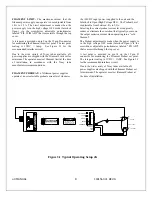
rear of the unit. See Figure 3.1, for a typical operating
setup.
The return line from the load should be connected to the
terminal on the rear of the power supply. Using a
separate external ground at the load is not recommended.
C)
Attach the output cable to the load.
D)
Plug the high voltage output cable into the front
of the supply and hand tighten the knurled collar.
E)
Options Note
: See section 5 for hook up and
operating instructions for the options on your unit.
Custom models may also require set up changes.
F)
For initial turn-on, set the programming voltage
to the zero voltage position.
G)
The input power cable may now be connected
and power applied. The POWER ON LED should light
up. No high voltage will be generated at this time.
H)
Close the INTERLOCK. The HIGH VOLTAGE
ON LED should light up and the output will slow start to
the preset level output voltage and/or output current.
NOTE: The uX series is equipped with a slow start
circuit that ramps the output up to its maximum setting in
approximately 4 seconds after the INTERLOCK is closed.
I)
To terminate the generation of output power,
open the INTERLOCK. In the HIGH VOLTAGE OFF
mode the power supply’s fault and interface circuits are
still active and the filament operates at the Preheat level.
J)
To turn off the power supply, disconnect the
power.
Summary of Contents for uX50P50
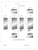
Page 16: ...uX MANUAL 4 118151 001 REV A Figure 2 1 50kV uX DIMENSIONS ...
Page 17: ...uX MANUAL 5 118151 001 REV A Figure 2 2 65kVuX DIMENSIONS ...
Page 21: ...uX MANUAL 9 118151 001 REV A Table 3 2 DC Input Filament Connections ...
Page 22: ...uX MANUAL 10 118151 001 REV A Figure 3 3 Monitors Voltage Current Control Connections ...
Page 23: ...uX MANUAL 11 118151 001 REV A Figure 3 4 Recommended Interlock HV on Configurations ...

