uX MANUAL
8
118151-001 REV A
FILAMENT LIMIT:
The maximum current that the
filament power supply can operate is user adjustable from
1.0A to 3.5A. The Limit adjustment is made when the
power supply is in the high voltage OFF mode (Interlock
Open) via the screwdriver adjustable potentiometer
labeled “FIL I LIM ADJ” that is accessible through the top
cover.
A test point is provided on pin 9 on the 15 pin D connector
for monitoring the Filament Limit set point. The test point
scaling is 1VDC = 1amp. See Figure 3.3 for the
recommended interface circuit.
Due to the wide variety of X-ray tubes available, uX
power supplies are shipped with the Filament Limit set for
minimum. The operator must set filament limit at the time
of installation in accordance with the X-ray tube
manufacturers recommendations.
FILAMENT PREHEAT:
uX filament power supplies
operate at a user selectable preheat current level whenever
the +24VDC input power is applied to the unit and the
Interlock is Open (High Voltage OFF). The Preheat Level
is adjustable from between .8A to 2.5A.
Selecting the correct preheat current level can greatly
reduce or eliminate the overshoot that typically occurs on
the output emission current when operating into a “cold
filament”.
The Preheat adjustment is made when the power supply is
in the high voltage OFF mode (Interlock Open) via the
screwdriver adjustable potentiometer labeled “PH ADJ”
that is accessible through the top cover.
A test point is provided on pin 14 on the 15 pin D
connector for monitoring the Filament Preheat set point.
The test point scaling is 1VDC = 1ADC. See Figure 3.3
for the recommended interface circuit.
Due to the wide variety of X-ray tubes available, uX
power supplies are shipped with the Filament Preheat set
for minimum. The operator must set filament Preheat at
the time of installation
.
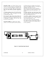
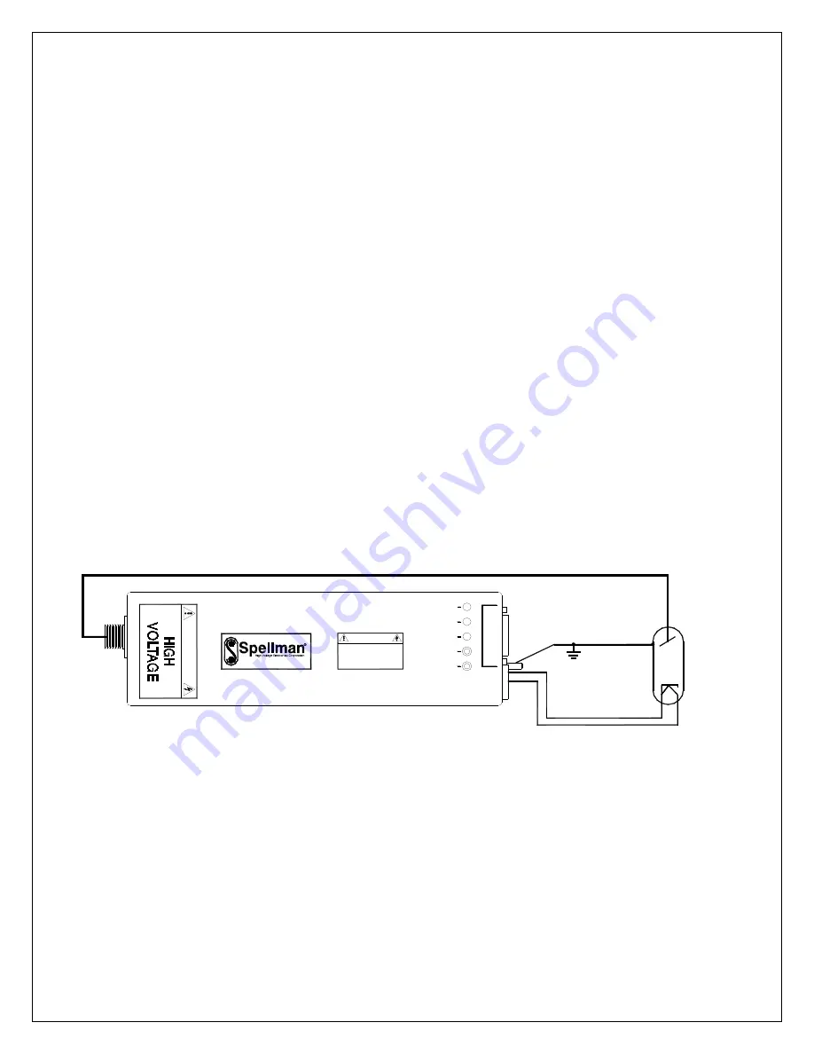
Figure 3.1 Typical Operating Setup uX
GND
+24V
DANGER
DANGER
AGAINST RISK OF FIRE
FOR CONTINUED PROTECTION
TYPE AND RATING FUSE.
REPLACE ONLY WITH SAME
mA ADJ
HV ON
kV ADJ
FIL I LIM ADJ
POWER ON
FIL OUT
FIL RET
I/O
FILAMENT
X-RAY TUBE
ANODE
Summary of Contents for uX50P50
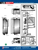
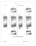
Page 16: ...uX MANUAL 4 118151 001 REV A Figure 2 1 50kV uX DIMENSIONS ...
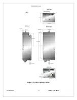
Page 17: ...uX MANUAL 5 118151 001 REV A Figure 2 2 65kVuX DIMENSIONS ...
Page 21: ...uX MANUAL 9 118151 001 REV A Table 3 2 DC Input Filament Connections ...
Page 22: ...uX MANUAL 10 118151 001 REV A Figure 3 3 Monitors Voltage Current Control Connections ...
Page 23: ...uX MANUAL 11 118151 001 REV A Figure 3 4 Recommended Interlock HV on Configurations ...

