PAGE 3 OF 5
SPELLMAN HIGH VOLTAGE ELECTRONICS CORPORATION
u
X
50W/65W/75W X-RAY
GENERATOR
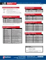
ANALOG INTERFACE CONNECTOR
MALE 15 PIN MINI “D”
PIN SIGNAL
PARAMETER
1 Monitor Return
Signal Ground
2 Voltage Monitor
0-10 volts = 0 to full scale, Zout=1KΩ
3 Current Monitor
0-10 volts = 0 to full scale, Zout=1KΩ
4 Interlock Output
Connect 12V HVON bulb to pin 15 to enable
5 +10 Volt Reference
+10 Volts at 1mA, maximum
6 Filament Monitor
1 volt = 1 amp, Zout=1KΩ
7 Voltage Program Input
0-10 volts = 0 to full scale, Zin=10MΩ
8 Local Voltage Program*
0-10 volts, screwdriver adjust
9 Filament Limit Setpoint*
1 volt = 1 amp, screwdriver adjust
10 Current Program Input
0-10 volts = 0 to full scale, Zin=10MΩ
11 Local Current Program*
10 turn pot, screwdriver adjust
12 Not used (+24V Out for Interlock) (Optional Interlock configuration)
13 Not used (Interlock Coil)
(Optional Interlock configuration)
14 Filament Preheat Setpoint*
1 volt = 1 amp, screwdriver adjust
15 Interlock Return
Interlock Ground
POWER INPUT/FILAMENT CONNECTOR
4 PIN PHOENIX CONTACT
PIN
SIGNAL
PARAMETER
1
+24V Input
+24 volts @ 5A, max.
2
24V Return (Gnd.)
Power Ground
3
Filament Out
0.3A to 3.5A, 5 volt, max.
4
Filament Return
Filament Return
HIGH VOLTAGE OUTPUT CONNECTOR
Spellman drywell type detachable connector.
Standard:
A one meter (39.4”) long polyethylene mating high
voltage cable is provided.
K5302:
A one meter (39.4”) long Mammoflex mating high voltage
cable is provided, SHV p/n 201946-007
K2001:
A one meter (39.4”) long Mammoflex mating high voltage cable
is provided, compatible with the XCC Option SHV p/n 201946-002
GRID BIAS CONNECTOR
2 PIN PHOENIX CONTACT
PIN
SIGNAL
PARAMETER
1
Ground
Chassis Ground
2
Grid Bias
0 to -300Vdc
How To Order:
Sample model number:
50 Watt unit: uX50P50
65 Watt unit: uX65P65
75 Watt unit: uX50P75
Options are added to the model number as follows:
uX50P50/XCC or uX50P75/GB
ETHERNET DIGITAL INTERFACE—
8 PIN RJ45 CONNECTOR
PIN
SIGNAL
SIGNAL PARAMETERS
1
TX+
Transmit Data +
2
TX-
Transmit Data -
3
RX+
Receive Data +
4
NC
No Connection
5
NC
No Connection
6
RX-
Receive Data -
7
NC
No Connection
8
NC
No Connection
RS-232 DIGITAL INTERFACE—
9 PIN FEMALE D CONNECTOR
PIN
SIGNAL
SIGNAL PARAMETERS
1
NC
No Connection
2
TX out
Transmit Data
3
RX in
Receive Data
4
NC
No Connection
5
SGND
Ground
6
NC
No Connection
7
NC
No Connection
8
NC
No Connection
9
NC
No Connection
USB DIGITAL INTERFACE—
4 PIN USB “B” CONNECTOR
PIN
SIGNAL
SIGNAL PARAMETERS
1
VBUS
+5 Vdc
2
D-
Data -
3
D+
Data +
4
GND
Ground
*Denotes 10 turn potentiometer accessable through holes in cover
Corporate Headquarters
Hauppauge, New York USA
+1-631-630-3000 FAX: +1-631-435-1620
e-mail: sales@spellmanhv.com
www.spellmanhv.com
128108-001 REV. A
Spellman High Voltage is an ISO 9001:2008 and ISO 14001:2004 registered company
Copyright © 2014 Spellman High Voltage Electronics Corp.
Note: The filament return wire cannot be grounded as this would short
circuit the tube return current monitoring to the uX. If grounding of the
filament is required, please consult the factory.
Summary of Contents for uX50P50
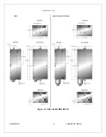
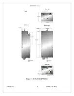
Page 16: ...uX MANUAL 4 118151 001 REV A Figure 2 1 50kV uX DIMENSIONS ...
Page 17: ...uX MANUAL 5 118151 001 REV A Figure 2 2 65kVuX DIMENSIONS ...
Page 21: ...uX MANUAL 9 118151 001 REV A Table 3 2 DC Input Filament Connections ...
Page 22: ...uX MANUAL 10 118151 001 REV A Figure 3 3 Monitors Voltage Current Control Connections ...
Page 23: ...uX MANUAL 11 118151 001 REV A Figure 3 4 Recommended Interlock HV on Configurations ...


