DF/FF MANUAL 118002-001 R
ev B
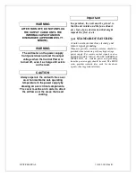
WARNING
Line voltage is present whenever the
power supply is connected to external
line voltages. Be sure to disconnect
the line cord before opening the unit.
allow 5 minutes for internal
capacitance to discharge before
removing any cover
.
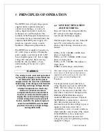
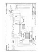
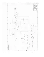
When K1 is energized, voltage is applied
to main rectifier bridge power module
CR1. Through the output of the diode
module, rectified AC is supplied to filter
Capacitor C1, a screw terminal type large
can electrolytic. C1 is initially charged
through inrush limiting circuitry located
on the Filament PWB. An LC circuit
comprised of HF film capacitor C2 and an
air core inductor L2 filter HF noise from
inverter.
4.2
INVERTER
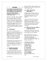
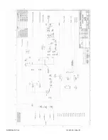
The inverter is an H bridge hybrid
topology. Current mode control is used for
driving the inverter. Two half-bridge
IGBT modules are used as switches in H
Bridge. These IGBTs provide high
frequency switching to control the
primary current flow. Typically they
operate at approximately 18kHz.
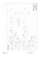
The IGBT driver board provides the gate
control of the switches. The system
control board generates gate drive control
signals. The IGBT gate driver PWB
provides the required gate voltages and
offsets.
4.3
HIGH VOLTAGE
TRANSFORMER
The output of the High Frequency Quasi-
resonant Inverter is connected to the
primary of the High Voltage Transformer.
The High Voltage Transformer is a step
up type. Typical secondary voltages are in
the range of 3kV to 16kV depending upon
output voltage ratings.
4.4
HIGH VOLTAGE
ASSEMBLY
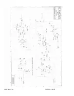
The High Voltage Assembly will vary
depending upon the model ordered. The
circuitry typically consists of a series
arrangement of full wave voltage
doublers.
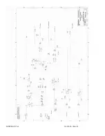
A high bandwidth resistive/capacitive
divider provides voltage feedback for
regulation and monitoring. A sense
resistor connected at the low voltage end
of the High Voltage Rectifier provides
current feedback for regulation and
monitoring.
4.5
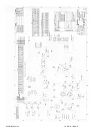
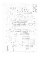
FRONT PANEL/SYSTEM
CONTROL PWB
Auxiliary DC voltages are generated in
low voltage power supply section of the
Front Panel/System Control PWB.
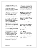
Front panel LEDs provide status
indication of the necessary diagnostics
needed for recognizing the
operation/shutdown mode of the
generator. Front panel LEDs display the
following information:
CONTROL POWER ON
EXT. INTERLOCK OPEN
OVER VOLTAGE
OVER POWER
MA RGLT ERROR
KV MIN ERROR
FIL CURR LIMIT
EXT INTERLOCK CLOSED
HIGH VOLTAGE ON
OVER CURRENT
KV RGLT ERROR
LEAKAGE LIMIT /TEMP
ARC
Summary of Contents for X3645
Page 1: ...DF FF MANUAL 1 118002 001 Rev B ...
Page 2: ...DF FF MANUAL 2 118002 001 Rev B ...
Page 28: ...DF FF MANUAL 118002 001 Rev B ...
Page 29: ...DF FF MANUAL 118002 001 Rev B ...
Page 30: ...DF FF MANUAL 118002 001 Rev B ...
Page 31: ...DF FF MANUAL 118002 001 Rev B ...
Page 32: ...DF FF MANUAL 118002 001 Rev B ...
Page 33: ...DF FF MANUAL 118002 001 Rev B ...
Page 34: ...DF FF MANUAL 118002 001 Rev B ...
Page 35: ...DF FF MANUAL 118002 001 Rev B ...
Page 36: ...DF FF MANUAL 118002 001 Rev B ...
Page 37: ...DF FF MANUAL 118002 001 Rev B ...
Page 38: ...DF FF MANUAL 118002 001 Rev B ...
Page 39: ...DF FF MANUAL 118002 001 Rev B ...
Page 40: ...DF FF MANUAL 118002 001 Rev B ...

