Page
38
of
98
118157-001 Rev C
Unpacking Generator:
The XRV Generator and subsystem components are shipped in padded containers to avoid damage
during shipment. All of the containers will have an indication that shows the correct orientation for
shipment and unpacking. The XRV Generator is surrounded within a foam padding to protect it from
shock and vibration during shipment. There are 6 bolts on the surrounding bottom of the crate that
need to be loosened in order to remove the XRV Generator. Do not remove the 4 bolts from the top of
the crate. Once the bolts are loosened, the top can be removed. Two people can lift the top of the crate
evenly from either end or a hoist and strap may be used instead. Visually inspect the XRV Generator for
any signs of damage once the top is removed. Report any damage to Spellman High Voltage. Include any
photos and a verbal description. The crate should not be exposed to moisture or extreme temperatures.
Loosen 6 Bolts on Bottom
of Generator Crate
XRV 160
Generator Crate
XRV 160 Generator
Lift Generator
from Handles
Summary of Contents for XRV Sub-system
Page 1: ...SPELLMAN HIGH VOLTAGE XRV SUBSYSTEM INSTALLATION MANUAL ...
Page 13: ...Page 13 of 98 118157 001 Rev C XRV 160kV Overview 400Vac 3Ø Input ...
Page 17: ...Page 17 of 98 118157 001 Rev C XRV225kV Overview XRV225 400Vac 3Ø 6kW Unit ...
Page 21: ...Page 21 of 98 118157 001 Rev C XRV450 Overview XRV450 Bipolar Cathode Generator ...
Page 22: ...Page 22 of 98 118157 001 Rev C XRV450 Overview XRV450 Bipolar Anode Generator ...
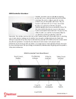
Page 28: ...Page 28 of 98 118157 001 Rev C XRVC Controller Overview XRVC Controller Rear Panel Detail ...
Page 51: ...Page 51 of 98 118157 001 Rev C System Grounding Detail and HV Cable Connections ...
Page 66: ...Page 66 of 98 118157 001 Rev C ...
Page 67: ...Page 67 of 98 118157 001 Rev C Power Source Connections Unipolar Basic ...
Page 68: ...Page 68 of 98 118157 001 Rev C Power Source Connections Unipolar Basic ...
Page 72: ...Page 72 of 98 118157 001 Rev C Power Connections I O System Interface Box ...
Page 76: ...Page 76 of 98 118157 001 Rev C Main Input Power Connections I O System Interface Box ...
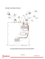
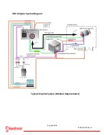
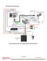
Page 77: ...Page 77 of 98 118157 001 Rev C I O Subsystem Interface Box System Diagram ...
Page 89: ...Page 89 of 98 118157 001 Rev C X Ray Tube Filament Calibration Setup ...


