Page
45
of
98
118157-001 Rev C
Non-spring loaded HV cable installation:
High Voltage Cable Installation (X-ray Tube):
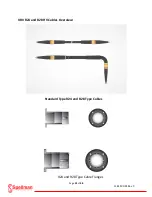
Wear nitrile gloves and obtain an X-ray tube cable flange. Wipe the flange with a lint free cloth and place
over a clean high voltage cable plug. (One cable flange will fit the X-ray tube and the other will fit the
XRV Generator). Rotate the flange counter clockwise on to the cable threads until it stops. Do not cross
thread the assembly. Insert the clean dry connector into the high voltage cable receptacle of the X-ray
tube with a small amount of force. Adjust the cable flange by rotating it clockwise until the flange is
approximately 1/2 inch from the X-ray tube mounting surface. Insert the gapping tool (5.5m – 6mm)
between the tube mounting surface and the flange. Rotate the flange until it is snug against the gapping
tool. Remove the gapping tool and rotate the flange slightly to align the mounting holes with the x-ray
tube holes. Tighten the grub screws of the cable flange to prevent any further rotation and remove the
plug from the receptacle. Apply 2 thin beads on opposite sides of the rubber cone. Distribute a thin coat
of silicone evenly on the entire cone. Finish the distribution by spreading in a circular fashion around the
circumference of the cone. Do not apply any silicone to the metal tip. If the silicone gets on the metal
tip, use a clean dry lint free cloth to remove it. Insert the HV cable plug into the receptacle until it seats
properly. Use the correct hardware and torque as per manufacturer specifications to tighten the cable
flange screws, alternating between the opposite placed screws.
Obtain flange
and HV cable
Place flange over
cable plug
Thread flange on
cable plug
Gapping tool for
R24 & R28 Cable
Insert dry HV cable
plug into X-ray tube
Measure distance
with gapping tool
Summary of Contents for XRV Sub-system
Page 1: ...SPELLMAN HIGH VOLTAGE XRV SUBSYSTEM INSTALLATION MANUAL ...
Page 13: ...Page 13 of 98 118157 001 Rev C XRV 160kV Overview 400Vac 3Ø Input ...
Page 17: ...Page 17 of 98 118157 001 Rev C XRV225kV Overview XRV225 400Vac 3Ø 6kW Unit ...
Page 21: ...Page 21 of 98 118157 001 Rev C XRV450 Overview XRV450 Bipolar Cathode Generator ...
Page 22: ...Page 22 of 98 118157 001 Rev C XRV450 Overview XRV450 Bipolar Anode Generator ...
Page 28: ...Page 28 of 98 118157 001 Rev C XRVC Controller Overview XRVC Controller Rear Panel Detail ...
Page 51: ...Page 51 of 98 118157 001 Rev C System Grounding Detail and HV Cable Connections ...
Page 66: ...Page 66 of 98 118157 001 Rev C ...
Page 67: ...Page 67 of 98 118157 001 Rev C Power Source Connections Unipolar Basic ...
Page 68: ...Page 68 of 98 118157 001 Rev C Power Source Connections Unipolar Basic ...
Page 72: ...Page 72 of 98 118157 001 Rev C Power Connections I O System Interface Box ...
Page 76: ...Page 76 of 98 118157 001 Rev C Main Input Power Connections I O System Interface Box ...
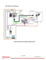
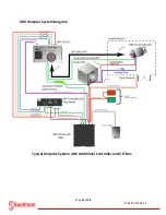
Page 77: ...Page 77 of 98 118157 001 Rev C I O Subsystem Interface Box System Diagram ...
Page 89: ...Page 89 of 98 118157 001 Rev C X Ray Tube Filament Calibration Setup ...


