background image

Instruction manual for compressor type HLF2/77 


Page 1 

PREFACE 

 
Sperre has produced this instruction manual in order to provide users of its compressor equipment 
with information about the compressor’s construction and operation, as well as basic information about 
inspection and maintenance. 
 
It is important that the operator should familiarise himself with the contents of this instruction manual, 
so as to ensure that installation, use and maintenance work is carried out in a correct and safe manner 
from the outset. 
 
The maintenance intervals and individual technical data are average values based on experience, and 
may vary, depending on the compressor’s operational parameters. 
 
The supplier accepts no responsibility for damage resulting from careless operation or inadequate 
maintenance. Keep the compressor in good mechanical condition, and remember that preventive 
maintenance of the equipment reduces the danger of damage and unnecessary operational 
interruptions. 
 
Sperre reserves the right to modify details without prior warning. 


Ellingsøy, January 2010 

Sperre Industri AS 


CONTENT 


Content Page 
 

Personal safety ............................................................................................................................ 2 
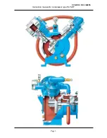
General description ..................................................................................................................... 2 
Sketch .......................................................................................................................................... 3 
Installation.................................................................................................................................... 4 
Starting up ................................................................................................................................... 5 
Operation ..................................................................................................................................... 5 
Stopping ....................................................................................................................................... 5 
Maintenance – Overhaul – Repairs ............................................................................................. 5 
 Valves 

....................................................................................................................................... 5 

 Piston 

and 

connecting rod ........................................................................................................ 6 

 Bearings 

Dismantling and Assembly ..................................................................................... 7 

 Coolers 

..................................................................................................................................... 8 

 Gaskets 

.................................................................................................................................... 8 

Recommended lubricating oil brands .......................................................................................... 9 
Table of normal pressures and temperatures ............................................................................. 9 
Maintenance routines .................................................................................................................. 10-11 
Fault tracing chart ........................................................................................................................ 12 
Tolerances – wear limits .............................................................................................................. 13 
Ordering spare parts .................................................................................................................... 14 
Spare parts list ............................................................................................................................. 15 
Available spare part kits .............................................................................................................. 16 
Illustration for spare parts list ....................................................................................................... 17-21 
  

CCG DOC NO. 346055 

Summary of Contents for HLF2/77

Page 1: ...HLF2 77 INSTRUCTION MANUAL AIR COMPRESSOR GB SPERRE CCG DOC NO 346055 ...

Page 2: ...ponsibility for damage resulting from careless operation or inadequate maintenance Keep the compressor in good mechanical condition and remember that preventive maintenance of the equipment reduces the danger of damage and unnecessary operational interruptions Sperre reserves the right to modify details without prior warning Ellingsøy January 2010 Sperre Industri AS CONTENT Content Page Personal s...

Page 3: ... is defective GENERAL DESCRIPTION This is a two cylinder two stage compressor The cylinders are fitted in a V shape at 90 angle to each other Cylinders and compressed air coolers are air cooled by a built in fan Supply pressure is determined by adjusting the safety valve The compressor and motor are normally supplied fitted together as a single unit The compressor and motor are connected by means ...

Page 4: ...Instruction manual for compressor type HLF2 77 Page 3 CCG DOC NO 346055 ...

Page 5: ... This applies to rigid mounting and flexible mounting alike A well dimensioned fresh air duct must be provided to the location where the compressor is installed The mouth of the duct should be as close as practically possible to the suction side of the cooling fan The ambient temperature should not exceed 45 C In principle the pipe from the compressor to the air reservoir should be arranged as sho...

Page 6: ... time to time MAINTENANCE OVERHAUL REPAIRS Only Sperre original spare parts should be used for overhauls and repairs Before ordering spare parts please read the instructions given in chapter Ordering spare parts Valves LP valve To dismantle the valve proceed as follows 1 Loosen pipe connections 2 Loosen and remove cylinder head 3 Loosen the bolts holding the valve in place on the cylinder head Car...

Page 7: ...omponent may lead to overheating and consequent damage The supplier accepts no responsibility for damage to the compressor resulting from the use of non original parts Only original Sperre copper gaskets can be used as valve seating gaskets Exact dimensions and correct hardness are of great importance for trouble free operation Cylinder head nuts should be tightened a little at a time in sequence ...

Page 8: ... C before sliding it onto the pin Gudgeon pin bearings Dismantle as follows 1 Remove seeger rings 2 Press out the gudgeon pin If necessary heat the piston slightly 3 Use a hydraulic press to remove and re install the gudgeon pin bearing in the connecting rod Important Check that there is axial play between connecting rod and piston after installation Main bearings Dismantle as follows 1 Remove the...

Page 9: ... then blowing them clean with compressed air In the case of heavy deposits of dirt the coolers should be dismantled for external and internal cleaning Any carbon deposits in the tubes can be removed by placing them in a bath of carbon remover or similar solvent overnight and then flushing with hot fresh water Important Make sure that the cleaning products are suitable for use on copper pipes Gaske...

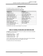
Page 10: ...HILLIPS COMPR OIL 68 SHELL CORENA AP 68 SHELL CORENA P 68 STATOIL FRIDGEWAY S 100 STATOIL COMPWAY 68 TOTAL LUBMARINE BARELF AL 100 TOTAL DACNIS P STATOIL COMPWAY SX68 Ask SPERRE for advice before using lubricating oil of any other type TABLE OF NORMAL PRESSURES AND TEMPERATURES Temperatures in service with shaft speed 1450 rpm The values are valid for ambient temperature 40 C and delivery pressure...

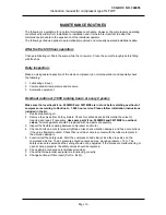
Page 11: ...according to Routine A 1 000 hour service Please follow installation instructions included in the kit 1 Replace lubricating oil 2 Remove the valves from both cylinders Check for carbon deposits Dismantle the valve for cleaning and repair if necessary Use spare part kit no 3036MK2 and 3037MK2 to overhaul valves All valve gaskets should be replaced with new parts at assembly 3 Inspect the flexible c...

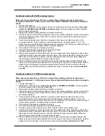
Page 12: ...gudgeon pins with bearings and crank bearings Rotate the shaft by hand and check that the main bearings are rotating smoothly and without any signs of excessive wear Use overhaul kit no 7933 Overhaul routine C 10 000 running hours Make sure that overhaul kit no 7963 are in stock before starting overhaul of compressor according to Routine C 10 000 hour service Please follow installation instruction...

Page 13: ...stem Compressor does not stop when air reservoir is full Check pressure switch and automatic circuitry Safety valve damaged or defective causing it to open at lower pressure Replace safety valve 3 Valves require maintenance too frequently Possible causes Remedy Overheating High ambient temperature Improve fresh air supply Carbon deposits in coolers Clean coolers Dirt or foreign matter in intake ai...

Page 14: ...g 0 015 0 04 mm 0 06 mm All other rings 0 00 0 025 mm 0 04 mm These values apply to both piston diameters 3 Clearance between piston and cylinder Measure the clearance by means of a dial gauge measuring the cylinder and piston separately Alternatively the piston can be placed in the cylinder and the clearance measured with thickness gauges The piston clearance should be measured in the area above ...

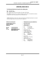
Page 15: ...d disclaims all legal liability in connection with such amendments Address for ordering parts SPERRE INDUSTRI AS 6057 ELLINGSØY NORWAY Phone 47 70 16 11 00 Fax 47 70 16 11 10 E mail industri sperre com www sperre com Original parts can also be ordered from Sperre Rotterdam BV Glasblazerstraat 12B NL 2984 BL Ridderkerk NETHERLANDS Tel 31 180 463 299 Fax 31 180 463 264 E mail rotterdam sperre com Sp...

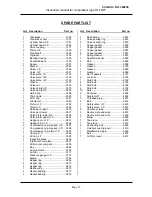
Page 16: ...2 Oil ring L P 3529 1 Inspection glass 3634 1 Intercooler complete 3657 1 After cooler complete 3658 1 Key 3682 1 Air relief valve 3700 1 Air filter 3711 1 Pressure gauge H P 3773 1 Nipple 3783 1 Seeger ring 3806 4 Seeger ring 3813 1 Seeger ring 3815 1 Ball bearing 3872 2 Needle bearing 3877 2 Needle bearing 3878 Qty Description Part no 1 Ball bearing 3881 1 Valve sealing ring 3918 2 Valve sealing...

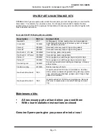
Page 17: ...ngs and or gaskets Overhaul kit LP valve 3036MK2 Valve springs plates and gaskets Overhaul kit HP valve 3037MK2 Valve springs plates and gaskets Piston LP 3354MK Piston gudgeon pin with Seeger rings and piston rings Piston HP 3352MK Piston gudgeon pin with Seeger rings and piston rings Connecting rod 1428MK Connecting rod with small and big end bearings oil scoop with set screw Flexible coupling 4...

Page 18: ...CCG DOC NO 346055 ...

Page 19: ...CCG DOC NO 346055 ...

Page 20: ...CCG DOC NO 346055 ...

Page 21: ...CCG DOC NO 346055 ...

Page 22: ...CCG DOC NO 346055 ...

Page 23: ...ri AS N 6057 Ellingsøy Norway Tel 47 70 16 11 00 Fax 47 70 16 11 10 industri sperre com Sperre Rotterdam BV Glasblazerstraat 12B NL 2984 BL Ridderkerk The Netherlands Tel 31 180 463 299 Fax 31 180 463 264 rotterdam sperre com www sperre com Sperre China Room 16E No 257 Siping Road Hongkuo District 200081 Shanghai China Tel 86 216 5070436 Fax 86 216 5070402 china sperre com CCG DOC NO 346055 ...

Reviews: