Instruction manual for compressor type HLF2/77
Page 2
PERSONAL SAFETY
The installation, operation and maintenance of the compressor should be carried out by trained
personnel who are familiar with the contents of this instruction manual.
The compressor must only be used to compress air.
Unauthorised remodelling or modification of the compressor may result in a safety hazard, and are not
permitted.
Before any form of work is commenced on the compressor the electrical power must be turned off at
the starter panel and at the main switchboard, and the switch on the main switchboard must be
marked with a notice indicating that repair work is in progress. The discharge valve of the compressor
must be closed, and the pressure must be released in all pressurised parts of the compressor.
The safety valves for LP and HP air and any other safety equipment must be inspected regularly.
Damaged components should be replaced with new, original parts. Adjustment of the safety valves
shall only be carried out by authorised personnel. The compressor must never be used if the safety
equipment is defective.
GENERAL DESCRIPTION
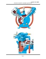
This is a two cylinder, two stage compressor. The cylinders are fitted in a V-shape at 90° angle to
each other. Cylinders and compressed air coolers are air-cooled by a built in fan. Supply pressure is
determined by adjusting the safety valve.
The compressor and motor are normally supplied fitted together as a single unit. The compressor and
motor are connected by means of a heavy duty flexible coupling.
All the materials used are of first class quality, thoroughly tested and in accordance with the
requirements of the classification societies.
Instrumentation is supplied in accordance with classification society requirements and if desired the
compressor can be fitted with equipment for fully automatic operation.
Bearings and cylinder walls are splash lubricated. The oil level in the sump can be checked through a
sight glass. An automatic low oil level alarm can be supplied as an optional extra.
The compressor is normally supplied without a relief mechanism for the LP cylinder suction valve.
However, a relief mechanism can be ordered from SPERRE if required.
The compressor unit can be supplied either for bolting directly to the foundation, or for flexible
installation by means of resilient mountings fitted under the bedplate.
CCG DOC NO. 346055
Summary of Contents for HLF2/77
Page 1: ...HLF2 77 INSTRUCTION MANUAL AIR COMPRESSOR GB SPERRE CCG DOC NO 346055 ...
Page 4: ...Instruction manual for compressor type HLF2 77 Page 3 CCG DOC NO 346055 ...
Page 18: ...CCG DOC NO 346055 ...
Page 19: ...CCG DOC NO 346055 ...
Page 20: ...CCG DOC NO 346055 ...
Page 21: ...CCG DOC NO 346055 ...
Page 22: ...CCG DOC NO 346055 ...

