Instruction manual for compressor type HLF2/77
Page 5
STARTING UP
Before initial starting up and after long periods out of use, carry out the following operations in the
sequence given:
1. Check the oil level (sight glass).
2. If the compressor has been out of service for more than 6 months, remove valves and lubricate
cylinder walls.
3. Open valves on compressed air line, and start the unit.
4. Check that all components are running normally. Inspect instruments, check for air leaks.
OPERATION
During operation, pressures and temperatures must be within the recommended limits. Any deviation
is abnormal and it’s cause should be ascertained by means of the fault tracing chart. In the case of
pressure or temperature deviations, it is recommended first to check the values with new
thermometers and pressure gauges in order to ensure that the fault is not to be found in the
instruments.
STOPPING
If the compressor is to remain unused for a long period, lubricate valves and cylinder walls with oil.
The compressor should be turned over from time to time.
MAINTENANCE – OVERHAUL – REPAIRS
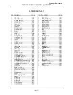
Only Sperre original spare parts should be used for overhauls and repairs. Before ordering spare parts,
please read the instructions given in chapter: “Ordering spare parts”.
Valves
LP valve
To dismantle the valve, proceed as follows:
1. Loosen pipe connections.
2. Loosen and remove cylinder head.
3. Loosen the bolts holding the valve in place on the cylinder head.
Carefully separate the upper and lower sections of the valve body to remove the valve insert with valve plates.
Important: There are milled slots in the upper and lower sections of the valve body. When the valve is
correctly assembled these slots correspond.
It is important that the valve is be correctly fitted under the cylinder head. The valves suction side should
be turned towards the suction air filter and the pressure side must face towards the fan/electric motor.
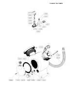
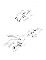
Press the valve (3036) against the cylinder head (1283) by means of a hydraulic press or vice. Force
approx. 2T. Tighten the screws (4401) to a torque of 24 Nm.
The screws 4401 must be locked so that they cannot come loose. The edge of each screw head has a
notch. After tightening the screws, lock them by putting a punch mark in the valve at each notch.
CCG DOC NO. 346055
Summary of Contents for HLF2/77
Page 1: ...HLF2 77 INSTRUCTION MANUAL AIR COMPRESSOR GB SPERRE CCG DOC NO 346055 ...
Page 4: ...Instruction manual for compressor type HLF2 77 Page 3 CCG DOC NO 346055 ...
Page 18: ...CCG DOC NO 346055 ...
Page 19: ...CCG DOC NO 346055 ...
Page 20: ...CCG DOC NO 346055 ...
Page 21: ...CCG DOC NO 346055 ...
Page 22: ...CCG DOC NO 346055 ...

