Always inspect your meter, test leads and accessories for any signs of damage or abnormality
before every use. If any abnormal condition exist: e.g. broken test lead, cracked case etc., do
not attempt to take any measurements. Return for repair to 245 Marcus Boulevard,
Hauppauge, NY 11788
DOUBLE INSULATION
WARNING:
TO AVOID ELECTRIC SHOCK, DISCONNECT
MEASURING TERMINALS BEFORE REMOVING BACK COVER.
CAUTION:
FOR CONTINUED PROTECTION AGAINST FIRE, REPLACE
ONLY WITH FUSE OF THE SPECIFIED VOLTAGE, CURRENT, AND RUPTURE
SPEED RATINGS.
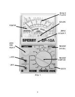
TO PLACE MINI-METER™ IN OPERATION:
A. BATTERY
1. A battery is furnished with each instrument. Remove back case and make certain it is in
place, in proper po and – is molded in well under battery.
2. For replacement, use "AA" battery.
3. If instrument is not in service for a long time, remove battery and store separately.
4. To avoid battery drain, always set Range knob at OFF position.
B. FUSE
1. A fuse is furnished with each instrument, installed in a fuse holder. Check to make sure
the fuse is securely in its clips at the time you check the battery.
2. For replacement, use A.W. Sperry Instruments Inc. Part # F-7 fuse.
CAUTION: DO NOT
short fuse out of the circuit, or use a fuse with a higher rating
than
Ω
amp., or alter circuit to eliminate fuse. These actions negate the safety purpose of the
Fuse, can cause damage to the instrument and or equipment being measured and or injury to
the user.
C. ZERO ADJUSTMENT
1. Before use and for greatest accuracy, make certain that the pointer is set exactly on the
Zero Line, at the extreme left of the arc.
2. If not on zero, rotate the Zero Adjuster Screw, at middle bottom of window, until pointer
is directly over the line zero.
3. It is good practice to check the zero adjustment daily, since changes in atmospheric
conditions can cause it to drift in position.
D. TESTLEADS
1. One (1) pair consisting of a Red Lead and a Black Lead, is furnished with
each instrument.
2. The short insulated probe tips fit into the two receptacles on the front cover.
3. The long insulated prod handles are used to make contact with the circuit
being measured.
4
!
!


