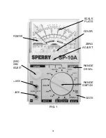
Before taking any measurements, ALWAYS REMEMBER TO
CAREFULLY CHECK THE FUNCTION DESIRED, THE POSITION OF THE ROTARY
SWITCH AND THE RANGE TO BE USED. START WITH THE HIGHEST RANGE AND WORK
DOWN TO LOWER RANGES UNTIL POINTER READS IN UPPER HALF OF SCALE.
MEASUREMENT PROCEDURE
To minimize possibility of damage to the instrument and to obtain a long trouble-free field
life, the following procedure is recommended.
E. ACCURACY
1. For best accuracy, the pointer should read in the upper half of the scale, preferably in
the fourth quadrant of the arc, where accuracy is best.
F. SWITCH POSITION
1. Prior to use, SET THE SWITCH TO THE HIGHEST RANGE OF THE FUNCTION TO
BE MEASURED.
Work down to lower successive ranges of this function until the pointer reads in the
upper half of the scale.
.
For example, in preparing to read AC volts, set the switch to highest range then take
measurement. Work the switch down to lower ranges of AC volts until the pointer reads in
the upper half of the arc.
.
In this fashion, the instrument is protected against overloads where circuit values are
not known.
2. When finished with measurements of one function, remove Test Leads COMPLETELY
from the circuit, if another different function is to be measured, FIRST set switch to the
highest range of the new function, THEN take measurements.
HOW TO READ AC VOLTS
1. Connect Red short probe in + Jack, Black in – Jack. Read all AC Volt Ranges on the
third arc down.
2. Voltage measurements are taken by connecting the instrument in parallel with the circuit
being checked. The long insulated prod handles are used to make contact with the circuit.
NOTE: For maximum safety, do NOT hold the Mini-Meter in your hand on the two highest
AC Volt ranges. (250 & 500V AC)
HOW TO READ DC VOLTS
1. Connect Red short probe into + Jack, Black in - Jack.
2. Read all DC volt range on the second arc down.
3. Voltage measurements are taken by connecting the instrument in parallel with the circuit
being checked. The long insulated prod handles are used to make contact with the circuit.
NOTE: For maximum safety do NOT hold the Mini-Meter in your hand on the two
highest DC Volt ranges. ( 250 & 500 VDC)
5


