background image

Summary of Contents for UTS 30

Page 1: ...R UTS 30 Single Station System Installation Planning Guide UP 9801 Rev 2...

Page 2: ...al obligation by Sperry regarding level scope or timing of functional implementation is either expressed or implied in this document It is further understood that in consideration of the receipt or pu...

Page 3: ...d from diskette by a SPERRY 8439 Double Sided Diskette Subsystem The functions of the UTS 30 can be further enhanced by program products and user progammability implemented through the low cost 8439 d...

Page 4: ...ns the latest information available to assist the customer in planning and making preparations for installation of the UTS 30 Single Station and the SPERRYLINK Model 30 Desk Station and associated per...

Page 5: ...Sperry regarding level scope or timing of functional implementation is either expressed or implied in this document It is further understood that in consideration of the receipt or purchase of this d...

Page 6: ...tem Installation Planning Guide PAGE STATUS SUMMARY ISSUE Update A UP 9801 Rev 2 Part Section Page Update Number Level Appendix H 1 2 Orig Appendix I 1 2 Orig Appendix J 1 2 Orig Appendix K 1 2 Orig A...

Page 7: ...CONFIGURATIONS 2 1 2 4 CASCADED CONFIGURATIONS 2 5 2 5 MIXED CONFIGURATIONS 2 5 2 6 UTS 30T AND SPERRYLINK MODEL 30T CONFIGURATIONS 2 5 2 7 UTS 30 X 25 PUBLIC DATA NETWORK CONFIGURATION 2 5 3 ENVIRONM...

Page 8: ...S 30 SINGLE STATION AND MODEL 35 PRINTER WITH STAND 5 11 5 15 SPACE LAYOUT OF UTS 30 SINGLE STATION WITH MODEL 25B PRINTER AND MODEL 35 PRINTER WITH STAND 5 12 6 CABLING CONSIDERATIONS 7 OTHER CONSIDE...

Page 9: ...2 11 Configuration of SPERRYLINK Model 30T Deskstation through the SL1 2 13 2 12 UTS 30 in an X 25 PDN Configuration 2 14 4 1 Power Plug Diagrams 4 3 5 1 Dimensions of UTS 30 Model 30T Desk Station a...

Page 10: ...single station with the twisted pair processor module UTS 30T and the SPERRYLINK Model 30T desk station will be referred to as the Model 30T This equipment is designed to be unpacked installed and te...

Page 11: ...ally little or no modification to existing site facilities is necessary for successful installation and operation In planning your site however you should consider the following factors The communicat...

Page 12: ...UTS 30 single stations at various places throughout your facility You may also need cable raceways or similar materials to protect loose cables that interconnect the equipment For additional informati...

Page 13: ...uipment arrives You should also consider providing additional storage facilities for the printer supplies and the reusable shipping containers Operator Training The UTS 30 Model 30T desk stations have...

Page 14: ...te Subsystem OperationNerification Guide UP 10201 SPERRY Model 15 Printer General Description UP 10699 SPERRY Model 15 Printer User Guide UP 10693 SPERRY Model 258 Printer General Description UP 10810...

Page 15: ...lation Planning Guide UP 9755 SPERRYLINK Office System DOPS 20 System Hardware Installation Guide UP 10897 SPERRY 8613 Signal Distribution Module Installation and Operation Guide UP 9873 SPERRY 2712 D...

Page 16: ...lines using modems 2 2 MULTIDROP CONFIGURATIONS Multidrop configurations figure 2 2 allow more than one terminal to share the same transmission line to a host processor A modem or DCM must be used to...

Page 17: ...M 50 0 FT 15 2 M 50 0 FT NOTE 2 UTS 30 UTS 30 WITH 8439 ISKETTE SUBSYSTEM MODEL 258 PRINTER MODEL 31 PRINTER 1 Up to two diskette subsystems can be connected to each UTS 30 3 For a transmission rate o...

Page 18: ...of 2400 to 3600 bits per second the maximum length is 3048 meters 10 000 feet For a transmission rate of 2400 bits per second or less the maximum cable length is 4572 meters 15 000 feet 2 If modems ar...

Page 19: ...S 8439 DISKETTE SUBSYSTEM NOTE 2 15 2 M 50 0 FT MODEL 31 PRINTER NOTE 3 1 For a transmission rate of 2400 to 3600 bits per second bps the maximum cable length is 3048 meters 10 000 feet For a transmis...

Page 20: ...gh the existing telephone lines in your building or through lines of the SL1 PBX system The data is transferred from the single stations to the SPERRY 8613 Signal Distribution Module SOM and then to t...

Page 21: ......

Page 22: ...OTE 21 MODEM OR DCM NOTE 3 15 2 M 50 0 FT UTS30 UP TO 15 SPERRY DISPLAY TERMINALS UTS 400 MODEM OR DCM NOTE 3 15 2 M 50 0 FT UTS40 1524 M 5000 FT UTS40 3 Up to three DCMs can be multidropped The numbe...

Page 23: ...tem Installation Planning Guide HOST PROCESSOR UP TO 24 SINGLE STATIONS UTS 30T EXISTING TELEPHONE LINES 8439 DISKETTE DRIVE PRINTER OPTIONAL OPTIONAL PUNCH DOWN BLOCK Figure 2 6 Configuration of UTS...

Page 24: ...STATION System Installation Planning Guide EXISTING TELEPHONE LINES DOPS 20 UP TO 24 DESK STATIONS PRINTER OPTIONAL 8439 DISKETTE DRIVE OPTIONAL PUNCH DOWN BLOCK SOM 9801 30 Figure 2 7 Configuration...

Page 25: ...DCP UP TO 24 DESK STATIONS EXISTING TELEPHONE LINES MODEL 30T 2712 DOCUMENT READER OPTIONAL PRINTER OPTIONAL 8439 DISKETTE DRIVE OPTIONAL PUNCH DOWN BLOCK UP 9801 Rev 2 SOM A01 10 Figure 2 8 Configur...

Page 26: ...TING TELEPHONE LINES UP TO 24 SINGLE STATIONS UTS 30T PRINTER OPTIONAL 8439 DISKETIE DRIVE OPTIONAL PUNCH DOWN BLOCK HOST PROCESSOR V 35 OR RS 232 MODEM V 35 OR RS 232 MODEM SOM 98111 31 Figure 2 9 Co...

Page 27: ...24 DESK STATIONS EXISTING TELEPHONE LINES MODEL 30T PRINTER OPTIONAL 8439 DISKETTE DRIVE OPTIONAL Northern Telecom Equipment PUNCH DOWN BLOCK UP 9801 Rev 2 A ADM V 35 INTERFACE SOM 9801 32 Figure 2 1...

Page 28: ...ATION EXISTING TELEPHONE LINES DESK STATION MODEL 30T DESK STATION MODEL 30T PRINTER OPTIONAL 8439 DISKETIE DRIVE OPTIONAL Northern Telecom Equipment 1100 HOST NOTE The number of deskstations is limit...

Page 29: ...0 SPERRY UTS 30 SINGLE STATION System Installation Planning Guide HOST PROCESSOR Gb MODEM PUBLIC DATA NETWORK 0 MODEM UTS 30 Figure 2 12 UTS 30 in an X 25 PON Configuration UP 9801 Rev 2 A 0 MODEM i 1...

Page 30: ...t are 16 to 32 degrees Celsius 60 to 90 degrees Fahrenheit and 20 to 70 percent relative humidity Temperature changes should not exceed 11 1 degrees Celsius 20 degrees Fahrenheit per hour as condensat...

Page 31: ...r imbalance grounding voltage differential caused by lightning or other serious electrical disturbances can damage equipment components To prevent such damage UTS 30 single stations Model 30T desk sta...

Page 32: ...l 30T 8439 diskette subsystem per drive Model 15 printer Model 258 printer Model 31 printer Model 35 printer 8609 terminal multiplexer 8610 direct connection module 8613 signal distribution module 271...

Page 33: ...ommunications equipment The branch circuits should be separately fused or equipped with appropriate circuit breakers These circuits must also be properly grounded If you are modifying power circuits o...

Page 34: ...Rev 2 A c E 125V 15A 250V 13A NEMA 5 15P BS 1363 1967 250V 6A SPERRY UTS 30 SINGLE STATION System Installation Planning Guide B D 250V 10A NEMA 6 15P Figure 1 Power Plug Diagrams 4 3 IEC 83 C5 SEV 101...

Page 35: ...Plug See Fig 4 1 Country None Malaysia No cable Netherlands or plug B New Zealand B Norway B Poland A Portugal E None Rumania B South Africa B Spain B Sweden c Switzerland B United Kingdom B United St...

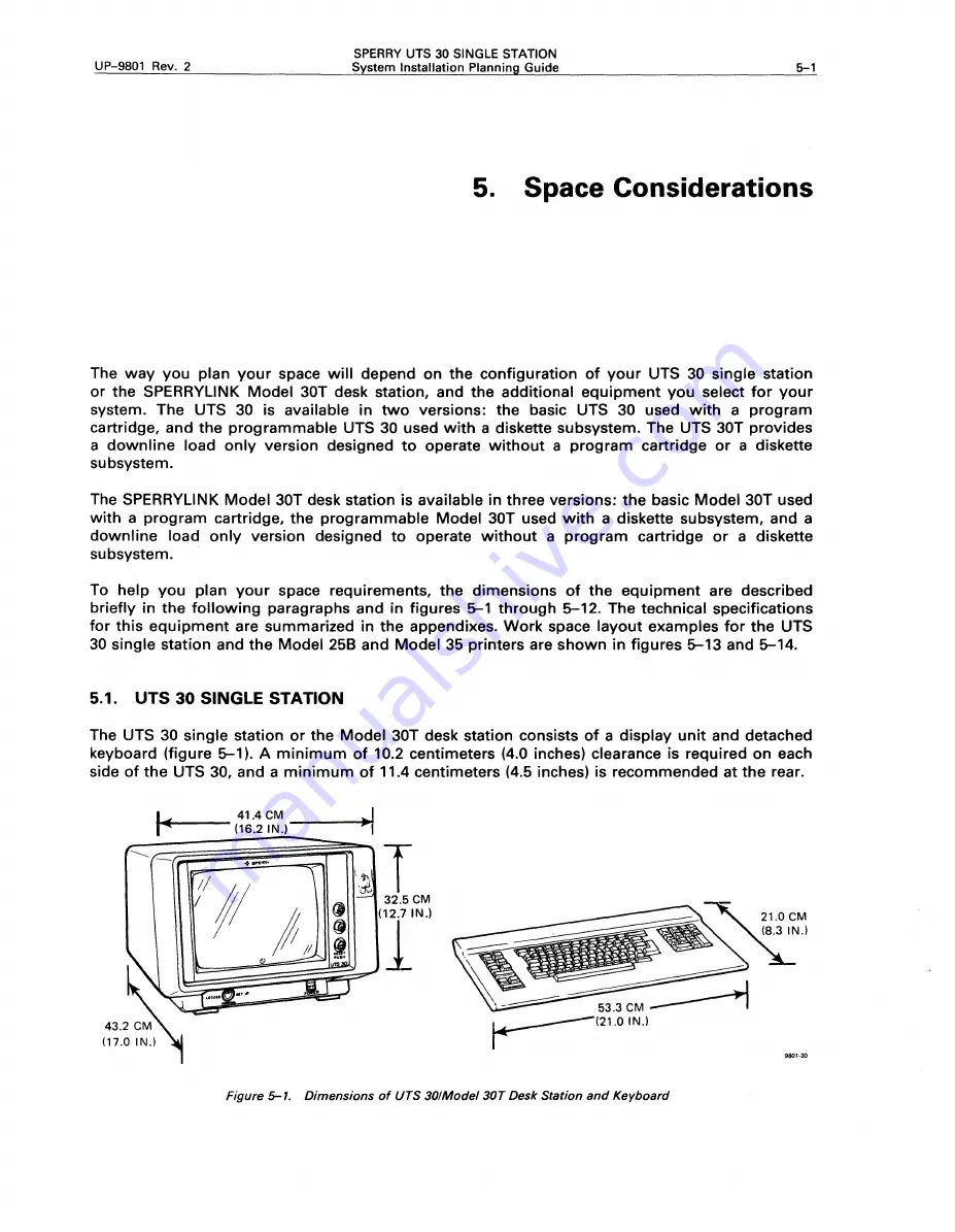
Page 36: ...ith a diskette subsystem and a downline load only version designed to operate without a program cartridge or a diskette subsystem To help you plan your space requirements the dimensions of the equipme...

Page 37: ...ate the magnetic stripe reader 21 6 MI 8 5 IN 11 1 CM 4 4 IN Figure 5 2 Dimensions of Magnetic Stripe Reader 5 3 8439 DOUBLE SIDED DISKETTE SUBSYSTEM 9801 13 The SPERRY 8439 Double Sided Diskette Subs...

Page 38: ...stands that facilitate bottom loading of paper The dimensions of each printer with its stand are briefly described in the following paragraphs and illustrated in figures 5 4 through 5 7 5 4 MODEL 15...

Page 39: ...81 3 centimeters 32 inches deep The stand has a slot for paper to feed into the printer from the bottom shelf while printouts accumulate on the shelf behind the printer A second slot at the rear of t...

Page 40: ...igure 5 6 is normally used with its own stand The stand has a slot for paper to feed into the printer from the bottom shelf while printouts accumulate on the top of the stand behind the printer The Mo...

Page 41: ...be used on a desktop or on an optional printer stand The stand has a slot for paper to feed into the printer from the bottom shelf while printouts accumulate on the top of the stand behind the printer...

Page 42: ...r can be installed on a desk or table The fan should be unobstructed with a minimum of 9 centimeters 3 inches between the fan and vent openings both sides and any surrounding structure 9801 19 Figure...

Page 43: ...on the wall to save space It can be installed in wiring closets in computer rooms under desks or in other out of the way places t The SOM comes with two host interface boards twisted pair or V 35 RS 2...

Page 44: ...h the Distributed Office Processing Station Model 20 DOPS 20 you will also need the SPERRY 8441 Mass Storage Subsystem The dimensions of this equipment are shown in figure 5 12 Refer to the DOPS 20 sy...

Page 45: ...t space has been allowed for operator comfort and efficiency The total space required is an area 152 4 centimeters 60 inches wide and 171 4 centimeters 67 5 inches deep I 63 0 CM 24 8 IN l 41 4 CM r 1...

Page 46: ...maintenance areas The equipment in this example requires an area 274 6 centimeters 108 inches wide and 171 4 centimeters 67 5 inches deep Your space requirements may vary depending on the equipment t...

Page 47: ...of 38 1 centimeters 15 inches at the rear for paper and 15 2 centimeters 6 inches on the sides for air circulation and removal of printouts Your space requirements may vary depending on the equipment...

Page 48: ...30 single station cable ordering bulletin UP 10101 for the cable feature numbers and to determine the length and the ordering number for each group of cables you need NOTE No cables are listed to con...

Page 49: ...a host system cannot exceed 60m 200 ft exceed 2 Total cable length from the UTS 30 to the diskette must 1524m 5 000 ft for transmission rate of 3600 9600 baud not exceed 2 7m 9 ft 3048m 10 000 ft for...

Page 50: ...t and 20 ft F8348 15 ft 25 ft 26 ft and 52 ft F8201 3 ft 10 ft 26 ft and 52 ft F8358 3 ft 10 ft 26 ft and 52 ft EXISTING TELEPHONE LINES 8439 DISKETTE F8292 SUBSYSTEM F8290 F8291 PRINTERS F8298 MODEL...

Page 51: ......

Page 52: ...ainer If you order a second diskette drive for the diskette subsystem it will be installed before the diskette subsystem is shipped Each of the printers will be packed in a separate shipping container...

Page 53: ......

Page 54: ...l quantities of UTS 30 single stations and associated equipment required for your installation 4 Prepare an initial layout showing locations of all equipment Scale drawings of this equipment are provi...

Page 55: ...tions Cables between each peripheral and its UTS 30 5 Use the current version of the UTS 30 ordering guide UP 9800 to order your UTS 30 and the UTS 4000 peripheral ordering guide UP 9897 to order your...

Page 56: ...uipment is installed 4 Determine the remote identifier RID system identifier SID and device identifier DID address codes for your equipment These codes are entered from the keyboard after the UTS 30 i...

Page 57: ...L J L J oo oo orn 0 EJ 0 oo 00 orn 0 0 0 o Jo D 00 00 orn G G 0 00 oo D E G o Jo O EJ oo 0 B B 0 E oo DD G 8 L J W locMI D D oo o G G 00 orn G 8 00 o Jo o EJ oo orn G 8 w EJ oo om E G oo o J b 00 D 00...

Page 58: ...e the voice recording for easier transcription if your desk station is connected to the SPERRY Voice Information Processing Station VIPS 9 2 EQUIPMENT The following list includes equipment you will ne...

Page 59: ...UP 9766 SPERRY Voice Information Processing Station Site Preparation Guide UP 9768 SPERRY Voice Information Processing Station Installation Guide 9 4 SPACE AND LOCATION CONSIDERATIONS No additional sp...

Page 60: ...ons for the Model 30 desk station with keyboard diskette subsystem and printers are provided in Section 5 9 5 ELECTROMAGNETIC INTERFERENCE Although the TIS cartridge has been certified to comply with...

Page 61: ......

Page 62: ...with tilt base Nominal 44 6 cm 17 5 in Maximum 49 0 cm 19 5 in ENVIRONMENTAL INFORMATION Maximum Heat Dissipation 120 kcal hr 140 watts Air Circulation Forced air fan Weight Without keyboard 20 0 kg 4...

Page 63: ...d User Circuits SPERRY UTS 30 SINGLE STATION System Installation Planning Guide Domestic 60 Hz 120 Vac single phase 2 wire and ground International 50 or 60 Hz 100 120 Vac single phase 2 wire and grou...

Page 64: ...LE STATION System Installation Planning Guide 53 3CM r 21 0 IN PERIPHERAL CABLE I I c 7 11 I 41 4 CM II 16 2 IN I I 24 1 CM FOR KEYBOARD I I I I 1 ALLOW THIS SPACE IJ g 5 IN _ ____L j 21 0 IN 980 JO F...

Page 65: ......

Page 66: ...ummary Data Recommended Clearances Front Rear Left Right Top Relative Humidity Range Operating 20 to 80 Shipping and Storage 38 1 cm 15 0 in 10 2 cm 4 0 in None required None required None required To...

Page 67: ...nning Guide FOR DISKETTE SUBSYSTEM WITH POWER SUPPLY ONLY OPTIONAL TO SECOND DISKETTE SUBSYSTEM 0 CJ CJ Cl CJr 36 3 CM 14 2 IN TOUTS 30 D 0 0 D 31 8 CM 12 5 IN 9801 31 Figure 8 1 8439 Double Sided Dis...

Page 68: ...5 in ENVIRONMENTAL INFORMATION Maximum Heat Dissipation 86 kcal hr 100 watts Temperature Range Operating 10 to 34 C 50 to 93 F Shipping and Storage Weight Without tractor With tractor 7 5 kg 16 6 lb...

Page 69: ...and ground International 50 or 60 Hz 100 120 Vac single phase 2 wire and ground or 50 or 60 Hz 220 240 Vac single phase 2 wire and ground 30 7 CM 12 1 IN 25 0 CMr 9 8 IN rrr l i 1 POWER CABLE FORMS T...

Page 70: ...ation at 117 watts 81 kcal hr 94 watts Air Circulation Forced air fan Weight Without forms tractor 16 7 kg 37 lb With forms tractor 19 kg 42 lb With cut sheet feeder 20 kg 49 2 lb Recommended Clearanc...

Page 71: ...se 2 wire and ground International 50 or 60 Hz 100 120 Vac single phase 2 wire and ground or 50 or 60 Hz 220 240 Vac single phase 2 wire and ground UP 9801 Rev 2 INTERFACE CABLE POWER CABLE 10 CM 4 IN...

Page 72: ...and Storage To 72 hours 40 to 62 C 40 to 144 F To 6 months 30 to 47 C 8 to 117 F Relative Humidity Range Operating 20 to 85 Shipping and Storage To 6 months 1 to 95 ELECTRICAL INFORMATION Power Requir...

Page 73: ...ION System Installation Planning Guide INTERFACE CABLE POWER CABLE UP 9801 Rev 2 3 7 CM 1 0 1 4 IN oQo 0 27 9 CM 11 0 IN oOo _j_ 0 4 5 CM 1 8 IN 1 2 7CM I 1 1 IN _ _ _ _ _ _ 39 6CM 15 6 IN 9801 34 Fig...

Page 74: ...ATION Power Requirements 0 22 kVA Approximately 220 watts Recommended User Circuits Weight 32 0 kg 70 lb Recommended Clearances Front As required by operator Rear 38 1 cm 15 in Sides 15 2 cm 6 in Top...

Page 75: ...1 2 0 IN SPERRY UTS 30 SINGLE STATION System Installation Planning Guide 60 5 CM 23 8 IN 65 5 CM 25 8 IN 51 0 CM 20 0 IN I 1 Figure F 1 Model 35 Printer Installation Planning View UP 9801 Rev 2 31 2...

Page 76: ...Air Circulation Natural convection ELECTRICAL INFORMATION Power Requirements 0 012 kVA Recommended Clearances Top Bottom Rear 1 0 cm 0 38 in 1 0 cm 0 38 in 10 2 cm 4 0 in Temperature Range 5 to 43 C...

Page 77: ...nning Guide 31 1 CM 12 3 IN I I 4 1 CM 1 6 IN I POWER CABl E I ______ UP 9801 Rev 2 Jl J2 I I I I L 1 L _______ J 10000001 I000000001 looooool I000000001 4 1 CM I 1 6 IN I 14 f g I 9801 36 Figure G 1...

Page 78: ...Maximum Heat Dissipation Minimum configuration 43 0 kcal hr 50 watts Maximum configuration 64 5 kcal hr 75 watts Air Circulation Natural convection ELECTRICAL INFORMATION Power Requirements 0 075 kVA...

Page 79: ...RY UTS 30 SINGLE STATION System Installation Planning Guide UP 9801 Rev 2 41 9 CM 06 S IN I POWER I CABLE I _ u J I 12 2 IN I i t Figure H 1 8609 Terminal Multiplexer Installation Planning View FRONT...

Page 80: ...tion Forced air fan ELECTRICAL INFORMATION Power Requirements 0 06 kVA 60 watts Recommended User Circuits Recommended Clearances 10 2 cm 4 0 in on all sides Temperature Range Operating 10 to 34 C 50 t...

Page 81: ...ystem Installation Planning Guide G I 4 5 CM 1 8 IN __________ 42 6 CM ______ 1 ___ 16 8 IN UP 9801 Rev 2 r 3 2 CM IN 1 3 _t_ 44 6 CM 17 6 IN t _ 6 9 CM 2 8 IN 9801 38 Figure 1 1 8613 Signal Distribut...

Page 82: ...t Dissipation 86 kcal hr 100 watts Temperature Range Operating 10 to 35 C 50 to 95 F Shipping and Storage To 72 hours 40 to 62 C 40 to 144 F To 6 months 22 to 47 C 8 to 117 F ELECTRICAL INFORMATION Po...

Page 83: ...TS 30 SINGLE STATION System Installation Planning Guide 0 c 2 0CM 0 8 IN I 3 8 CM l 1 5 IN I 42 2 CM 16 6 IN I I 53 3 CM 21 0 IN 2 0 cM 0 8 IN 11 2 cM N 4 4 I 9801 39 Figure J 1 2712 Document Reader I...

Page 84: ...p to 72 hours 40 to 62 C 40 to 144 F Up to 6 months 22 to 47 C 8 to 117 F ELECTRICAL INFORMATION Power Requirements 0 26 kVA 26 watts Recommended User Circuits Recommended Clearances Front Rear Withou...

Page 85: ...30 SINGLE STATION System Installation Planning Guide UP 9801 Rev 2 l_ r1I I I 19 1 CM IJ 1 1 4 52 6 CM __ 7 _ 5 _ 1 _N_ _ _ 21 5 IN Figure K 1 DOPS 20 Processor Installation Planning View 47 0 CM N 1...

Page 86: ...t Recommended Clearances 42 6 cm 16 8 in 15 9 cm 6 25 in 44 6 cm 17 6 in 12 2 kg 27 lb Front As required for operating Rear As required for cabling Sides None required Top None required Power Cord Len...

Page 87: ...Domestic 60 Hz 120 Vac single phase 2 wire and ground International 50 or 60 Hz 110 120 Vac single phase 2 wire and ground or 50 or 60 Hz 220 240 Vac single phase 2 wire and ground 1 3 2 CM IN 1 3 D...

Page 88: ...erience Professional ___ Knowledgeable ___ Novice With what system is the equipment used How do you use this manual As a reference source D As a classroom text O Please rate this manual As a reference...

Page 89: ...l the form to us Your reply will Qe carefully reviewed by the persons responsible for writing and publishing this manual 1 1 I Bus IN Ess RE p Ly MAIL NO POSTAGE STAMP NECESSARY IF MAILED IN THE UNITE...

Reviews: