8
3. Insert the test leads into the "COM" and "V-Ω" jacks.
Connect the two ends of the test leads together.
4. Place the range selector switch into the off position.
Nothing will appear on the display. Replace the range selector
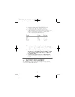
switch into the following ranges shown in the chart below.
Check for the appropriate meter response.
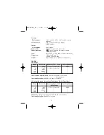
Range
Display
Readings
DC
NO
AC
NO
Ω
10.00
“1” flashing
DIODE
1.500
Approx.
5. As you can see, the decimal point moves as the ranges are
changed. The maximum display reading is 1999. The 200DCV
range will actually only read 199.9Vdc. We call this the 200DCV
range for convenience only.
6. You can now check the decimal point on each range by
referring to sec. 3 Specifications where the ranges are all listed.
Refer to the Range and Resolution columns to compute the
decimal point location.
7. If any abnormal conditions exist, do not attempt to take any
electrical measurements. Instead refer to sec. 14 Return for
Repairs.
Sec. 7
BATTERY REPLACEMENT
The DM-4400A has a self-contained power supply consisting of One 9V
Transistor Type Battery (NEDA #1604).
8
DM4400 04_06 5/3/06 1:10 PM Page 11


