RAIS
056357/B
In- and Output Calibration
6-15
General Remarks on Calibration
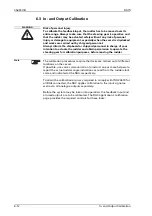
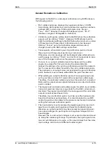
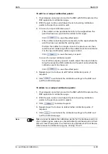
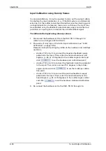
With regard to the RAC in- and output calibration using SUSI, observe
the following points:
•
Port rudder angles are displayed as negative numbers in SUSI.
Accordingly, port angles must also be entered as negative numbers,
prefixed with a minus sign. Starboard angles carry no sign.
Thus, “-45.0°” denotes an angle of 45 degrees to port, “45.0°”
denotes an angle of 45 degrees to starboard.
•
Calibration settings are written back to the RAC when the calibration
page is quit by clicking “Finish”. However, SUSI refuses to write
back the calibration settings to the RAC before the minimum number
of three input and three output calibration points has been set.
Clicking “Cancel” quits the calibration page and discards all
changes, leaving the RAC settings untouched.
•
Consequently, when deleting existing calibration points, at least
three input and three output points must remain set.
Otherwise, an error message will be displayed when attempting to
quit the page by clicking “Finish” and it will not be possible to save
any of the changes made since the page was entered.
•
Once an in- or output calibration point has been set, the rudder
angle value stored for this point cannot be altered directly.
Instead, the settings of an existing calibration point will be overwrit-
ten if a new point is added for exactly the same rudder angle value.
The analogue in- or output values associated with a given calibration
point, however, may be freely edited after the point has been set.
•
When adding an output calibration point, all analogue outputs are
set to provide a nominal 0 V signal at the respective rudder angle.
Therefore, the indicated rudder angle must be read at all connected
RAIs and the output values adjusted whenever an output calibration
point is added.
•
The largest port and starboard rudder angles for which input calibra-
tion points exist are taken as range limits for the RAC’s internal rud-
der scale. The angles transmitted at the analogue and the serial data
outputs cannot exceed these limits.
Therefore, input calibration points must be set at the hardover star-
board and hardover port positions. It is recommended to use NFU
control to position the rudder to the absolute mechanical limit when
setting the hardover calibration points.
•
The input polarity may be reversed by applying positive input volt-
ages for port angles and negative voltages for starboard angles.
Likewise, an output’s polarity may be reversed by generating posi-
tive output voltages for port angles and negative voltages for star-
board angles.
However, the in- and output voltages must ascend or descend stead-
ily along the rudder angle range. In particular, the input signal curve
may not exhibit peaks or troughs, as this would imply that the same
input voltage could occur at different rudder angles.
Summary of Contents for Rudder Angle Indicator System
Page 18: ...056357 B RAIS 1 10 Declaration of Conformity...
Page 20: ...056357 B RAIS 2 2 Normal Operational Mode...
Page 26: ...056357 B RAIS 3 6 Viewing RAC Errors through SUSI...
Page 28: ...056357 B RAIS 4 2 Maintenance by Service Personnel...
Page 58: ...056357 B RAIS 7 4 General Troubleshooting Instructions...
Page 64: ...056357 B RAIS 8 6 Replacing Alarm Output Relays...
Page 95: ......
Page 96: ......
Page 97: ......
Page 98: ......
Page 99: ......
Page 100: ......
Page 101: ......
Page 102: ......
Page 103: ......
Page 104: ......
Page 105: ......
Page 106: ......
Page 107: ......
Page 108: ......
Page 109: ......
Page 110: ......
Page 111: ......
Page 112: ......
Page 113: ......
Page 114: ......
Page 115: ......


