056357/B
RAIS
6-16
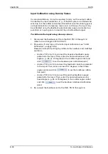
In- and Output Calibration
Initial Calibration
As delivered from the factory, the RAC is not yet able to take up normal
operation. At least three input and three output calibration points must
be set to make the outputs become functional.
Sperry Marine recommends to carry out an initial calibration directly
after the basic configuration parameters have been set.
During this initial calibration, input calibration points are to be set at the
hardover and midships rudder positions. Output calibration points are
then to be set for the hardover and rudder midships indications. After
this initial calibration, it is always possible to set further calibration
points or to edit existing ones.
Providing that the feedback unit has been carefully adjusted mechani-
cally and that the RAIs do not exhibit severe non-linearities, the initial
calibration should already result in sufficient calibration accuracy in
many cases.
During a performance check according to ISO_20673, the angles shown
by the RAIs will be recorded at every 5° for a ±45° steering gear and
every 10° for a ±70° steering gear. To meet the required accuracy, the dif-
ference between the angles of the transmitter shaft (rudder stock) and
the corresponding value shown at the RAIs is to be less than 1.5% of the
indicators’ full scale value.
Should this accuracy not be attained after the initial calibration, addi-
tional calibration points need to be set.
Errors affecting all outputs, including the serial data outputs, are cor-
rected by setting additional input calibration points. Errors affecting
individual analogue outputs only are corrected by setting additional out-
put calibration points
Such additional points may be set systematically at every 5° for a ±45°
steering gear and every 10° for a ±70° steering gear. This ensures opti-
mum calibration for the angles at which the accuracy is tested according
to ISO_20673.
Alternatively, it is also possible to determine the rudder angles where
the largest errors occur and to set calibration points at exactly these
angles. By repeating this procedure until the required accuracy is met,
good results are achieved with as few calibration points as possible.
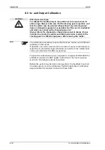
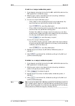
WARNING
Risk of personal injury
To calibrate the feedback input, the rudder has to be moved over its
entire range. Always make sure that the steering gear is operative and
that the rudder may be actuated safely without any risk of personal
injury or damage to equipment, especially when the vessel is drydocked
and works are carried out by shipyard personnel.
Always inform the shipboard or shipyard personnel in charge of your
intention to actuate the rudder and obtain permission to operate the
steering gear for calibration purposes, before moving the rudder.
Note
The calibration procedures require that tasks are carried out at different
locations on the vessel.
If possible, use voice communication to instruct one or more helpers to
report the actual rudder angle indications as read from the rudder stock
scale and indicated at the RAIs respectively.
Summary of Contents for Rudder Angle Indicator System
Page 18: ...056357 B RAIS 1 10 Declaration of Conformity...
Page 20: ...056357 B RAIS 2 2 Normal Operational Mode...
Page 26: ...056357 B RAIS 3 6 Viewing RAC Errors through SUSI...
Page 28: ...056357 B RAIS 4 2 Maintenance by Service Personnel...
Page 58: ...056357 B RAIS 7 4 General Troubleshooting Instructions...
Page 64: ...056357 B RAIS 8 6 Replacing Alarm Output Relays...
Page 95: ......
Page 96: ......
Page 97: ......
Page 98: ......
Page 99: ......
Page 100: ......
Page 101: ......
Page 102: ......
Page 103: ......
Page 104: ......
Page 105: ......
Page 106: ......
Page 107: ......
Page 108: ......
Page 109: ......
Page 110: ......
Page 111: ......
Page 112: ......
Page 113: ......
Page 114: ......
Page 115: ......


