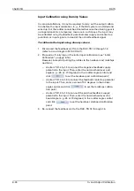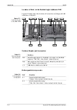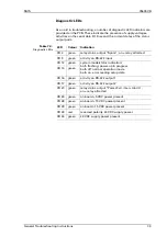
056357/B
RAIS
6-18
In- and Output Calibration
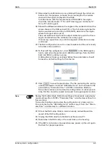
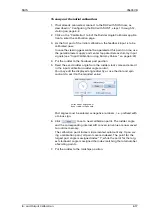
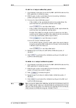
8. Read the exact rudder angle from the rudder stock scale and enter it
in the input calibration rudder angle control:
9. Click
to set a new calibration point.
10. Put the rudder to the hardover starboard position.
11. Read the exact rudder angle from the rudder stock scale and enter it
in the input calibration rudder angle control:
12. Click
to set a new calibration point.
13. Check that all input calibration points have been stored correctly:
The calibration point index should now read “4”.
Scroll down the list of calibration points with the spin control and
verify that:
–
For points 1 to 3, the rudder angles displayed are those you
entered for the hardover and midships positions. The input con-
trols will be greyed-out for the saved points.
–
For each point, the number shown below the “Delete” and
“Save” button lies between 0 and 4095 and is largest for the har-
dover port and smallest for the hardover starboard value:
This number represents the 12-bit A/D conversion value of the
input voltage, at the moment when the respective calibration
point was saved.
enter exact angle read
from rudder stock scale
enter exact angle read
from rudder stock scale
feedback signal
A/D conversion value
Summary of Contents for Rudder Angle Indicator System
Page 18: ...056357 B RAIS 1 10 Declaration of Conformity...
Page 20: ...056357 B RAIS 2 2 Normal Operational Mode...
Page 26: ...056357 B RAIS 3 6 Viewing RAC Errors through SUSI...
Page 28: ...056357 B RAIS 4 2 Maintenance by Service Personnel...
Page 58: ...056357 B RAIS 7 4 General Troubleshooting Instructions...
Page 64: ...056357 B RAIS 8 6 Replacing Alarm Output Relays...
Page 95: ......
Page 96: ......
Page 97: ......
Page 98: ......
Page 99: ......
Page 100: ......
Page 101: ......
Page 102: ......
Page 103: ......
Page 104: ......
Page 105: ......
Page 106: ......
Page 107: ......
Page 108: ......
Page 109: ......
Page 110: ......
Page 111: ......
Page 112: ......
Page 113: ......
Page 114: ......
Page 115: ......


