RAIS
056357/B
General Troubleshooting Instructions
7-3
Diagnostic LEDs
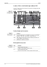
As an aid in troubleshooting, a number of diagnostic LED indicators are
provided on the PCB. These indicate the presence of supply voltages,
activities on the serial data I/O lines and the current states of the status
output ports.
Table 7-3:
Diagnostic LEDs
LED
Colour
Indication
CR 4
green
relay status output “Spare”; on = relay attracted
CR 9
green
activity on RS-422 input
CR 12
green
system mode/status indication:
both flashing: power-up in progress
both off: normal operation mode
both on: error reading setup data
CR 13
green
CR 16
green
activity on RS-422 output 1
CR 17
green
activity on RS-422 output 2
CR 20
green
relay status output “Power Fail. / Gen. Alarm”;
on = relay attracted
CR 23
green
on-board +5 VDC power present
CR 28
green
on-board +15 VDC power present
CR 29
green
on-board –15 VDC power present
CR 33
red
reversed polarity 24 VDC supply power
CR 34
green
24 VDC supply power present
Summary of Contents for Rudder Angle Indicator System
Page 18: ...056357 B RAIS 1 10 Declaration of Conformity...
Page 20: ...056357 B RAIS 2 2 Normal Operational Mode...
Page 26: ...056357 B RAIS 3 6 Viewing RAC Errors through SUSI...
Page 28: ...056357 B RAIS 4 2 Maintenance by Service Personnel...
Page 58: ...056357 B RAIS 7 4 General Troubleshooting Instructions...
Page 64: ...056357 B RAIS 8 6 Replacing Alarm Output Relays...
Page 95: ......
Page 96: ......
Page 97: ......
Page 98: ......
Page 99: ......
Page 100: ......
Page 101: ......
Page 102: ......
Page 103: ......
Page 104: ......
Page 105: ......
Page 106: ......
Page 107: ......
Page 108: ......
Page 109: ......
Page 110: ......
Page 111: ......
Page 112: ......
Page 113: ......
Page 114: ......
Page 115: ......


