056357/B
RAIS
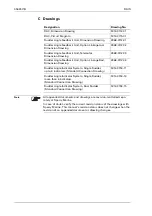
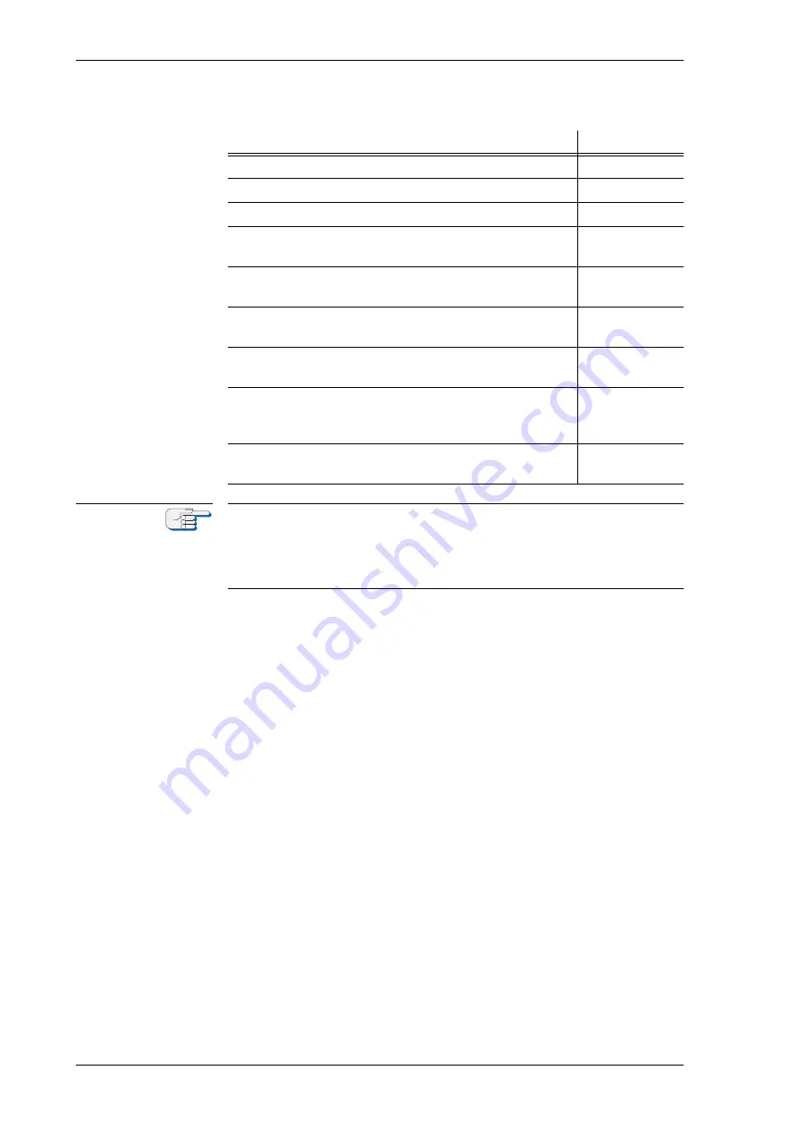
C Drawings
Designation
Drawing No.
RAC, Dimension Drawing
5014-0112-01
RAC, Circuit Diagram
5014-0115-01
Rudder Angle Feedback Unit, Dimension Drawing
4968-0112-01
Rudder Angle Feedback Unit, Option Linkage rod,
Dimension Drawing
4968-0112-02
Rudder Angle Feedback Unit, Telemotor,
Dimension Drawing
4968-0112-03
Rudder Angle Feedback Unit, Option Linkage Rod,
Dimension Drawing
4968-0112-04
Rudder Angle Indicator System, Single Rudder,
up to 6 indicators (Standard Connection Drawing)
5014-0153-11
Rudder Angle Indicator System, Single Rudder,
more than 6 indicators
(Standard Connection Drawing)
5014-0153-13
Rudder Angle Indicator System, Dual Rudder
(Standard Connection Drawing)
5014-0153-15
Note
All appended documents and drawings are revision-controlled sepa-
rately at Sperry Marine.
In case of doubt, verify the current revision status of the drawings with
Sperry Marine. This manual’s revision status does not change when the
revision of an appended document or drawing changes.
Summary of Contents for Rudder Angle Indicator System
Page 18: ...056357 B RAIS 1 10 Declaration of Conformity...
Page 20: ...056357 B RAIS 2 2 Normal Operational Mode...
Page 26: ...056357 B RAIS 3 6 Viewing RAC Errors through SUSI...
Page 28: ...056357 B RAIS 4 2 Maintenance by Service Personnel...
Page 58: ...056357 B RAIS 7 4 General Troubleshooting Instructions...
Page 64: ...056357 B RAIS 8 6 Replacing Alarm Output Relays...
Page 95: ......
Page 96: ......
Page 97: ......
Page 98: ......
Page 99: ......
Page 100: ......
Page 101: ......
Page 102: ......
Page 103: ......
Page 104: ......
Page 105: ......
Page 106: ......
Page 107: ......
Page 108: ......
Page 109: ......
Page 110: ......
Page 111: ......
Page 112: ......
Page 113: ......
Page 114: ......
Page 115: ......


