8 Servicing work
NGW 300 / LGW 300 / GBW 300
802
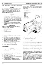
8.5.1 Disassembling and mounting the burner head
CAUTION
The ignition spark generator is operated at high voltage.
Before disassembly, the wiring harness plugs in the
vehicle must be disconnected. Otherwise, there is a
danger of death. If the burner head is mounted again,
reconnect the plugin the vehicle
ATTENTION
•
Basically, it is necessary to disconnect not only the
electrical connection to the temperature limiter and
the regulating thermostat, but also the electrical
connection from the vehicle to the control unit, and to
loosen the reference pressure line connectors and the
gas supply hose on the burner side. Otherwise,there
is a risk of damage to the burner and/or the electrodes
during the repair.
•
Pull out the burner head carefully from the heat
exchanger and slide it in order to prevent its being
damaged.
PLEASE NOTE
When the burner head is dismounted, the following
components become accessible:
–
Ignition electrodes
–
Flame monitor electrode
–
Fuel pipe
–
Combustion chamber
8.5.1.1 Disassembly
1. Disconnect the electrical line from the control unit to
the vehicle.
2. Disconnect the electrical lines to the temperature
limiter and the regulating thermostat (1, fig. 801).
3. Loosen the gas supply hose (6) and the reference
pressure line (7), if they are connected.
4. Loosen both nuts (4) so far that it is possible to
remove the screws (3) by swiveling.
5. Remove the screws (3) by swiveling.
6. Carefully dismount the burner head (5).
8.5.1.2 Mounting
ATTENTION
During the following procedure, please ensure that the
ignition electrodes and the flame monitor electrode
are not twisted.
1. Slide the burner head (5, fig. 801) carefully (5, fig. 801)
into the reassembly position.
2. Swivel in the screws (3).
3. Tighten both nuts (4) with 7.5 Nm.
4. Attach the gas supply hose (6) and, if applicable, the
reference pressure line (7).
5. Re-establish electrical connections (1) to the
temperature limiter and the regulating thermostat.
PLEASE NOTE
Ensure that the temperature limiter’s and the regulating
thermostat’s electrical connections are wired, using the
proper colours.
6. Re-establish the electrical connection to the vehicle’s
wiring harness.
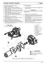
Fig. 801 Dismantling and mounting the burner head
8.6
Visual inspections and.
installation regulations
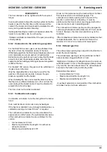
8.6.1 Connection to the vehicle’s cooling system
The heater must be installed in as low a position as
possible, so that the heater and the circulating pump are
sure to be bled automatically. This is particularly
applicable, as the circulating ump is not self-priming.
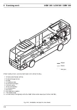
As shown in fig. 802, the heater must be connected to the
vehicle’s cooling system. The amount of coolant present
in the circuit must amount to 10 l at least.
In the vehicle’s cooling system, only only high pressure
valves with an opening pressure of at least 0.4 bar and
max. 2.0 bar are used.
Basically, the coolant hoses provided by Spheros must be
used. If this is not the case, the hoses must conform to the
DIN 73411 standard, at least. Hoses are to be installed
free of kinks (for flawless bleeding) and going upwards, if
possible. Hose connections must be secured with hose
clamps to prevent them from slipping.
1 Electrical connections
2 Split pin (2)
3 Screw
4 Nut (2)
5 Burner head
6 Gas connection
7 Reference pressure
1
2
3
4
5
6
7

