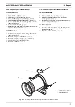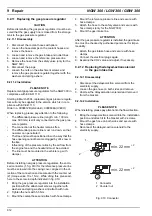
NGW 300 / LGW 300 / GBW 300
9 Repair
907
9.2.5 Replacing ignition electrodes
9.2.5.1 Disassembly
1. Dismount the burner head (see 8.5.1.1).
ATTENTION
During the following procedure, please ensure that the
ignition electrodes and the flame monitor electrode
are not twisted.
2. 2.Remove the cylinder screws (6, fig. 907) and
dismount the heat shield (5).
3. Remove the cylinder screws (4) and pull out the
ignition electrodes (3) approx.2 cm.
4. Remove electrical cionnections from the ignition
electrodes (3).
5. Remove the ignition electrodes (3) and the gasket (2).
6. Implement the measures for components when the
system is disassembled (see 9.1.1).
9.2.5.2 Installation
1. Position the ignition electrodes (3, fig. 907) with a new
gasket (2) at the installation space, create electrical
connections to the ignition electrodes (3) and push the
rubber sleeves up.
PLEASE NOTE
The rubber sleeves must be pushed up agains the gasket.
Otherwise there is a risk of spark-over von due to moisture.
2. Attach the ignition electrodes (3) with cylinder screws
(4). Tighten the screws with 5.5 Nm.
ATTENTION
ImDuring the following procedure, please ensure that
the ignition electrodes and the flame monitor
electrode are not twisted.
3. Attach the heat shield (5) with cylinder screws
(6).Tighten the screws with 5.5 Nm.
4. Check the spacing of the ignition electrodes (see
6.3.3).
5. Check the spacing of the flame monitor electrode (see
6.3.4).
6. Mount the burner head (see 8.5.1.2).
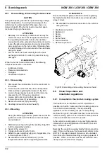
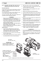
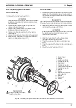
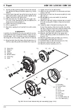
Fig. 907 Replacing the ignition electrodes, the flame monitor electrode and the burner
1
2
3
4
5
6
7
8
9
10
11
12
1
1
1
1
PLEASE NOTE
Coat the screws with Copas-
lip before mounting
1 Burner head
2 Gasket
3 Ignition electrodes
4 Cylinder screw (2)
5 Heat shield
6 Cylinder screw (4)
7 Flame monitor electrode
8 Cylinder screw (2)
9 Gasket
10 Burner
11 Spacer piece (4) with
safety washer
12 Gasket
13 Back wall
14 Sleeve
14
13

