9 Repair
NGW 300 / LGW 300 / GBW 300
910
9. Coat the sealing surfaces between the motor bracket
(16) and the fan casing (25) with a sealant (e.g. Loctite
396003).
10. Join the motor bracket (16) and the fan casing (25) and
attach with cylinder screws (27) and lock washers (28).
11. Tighten the screws (27) with 5.5 Nm.
12. Place the motor (4), the flange (6) and the gas mixer
(1) in the correct reassembly position and attach with
screws (8) and lock washers (7).
13. Tighten the screws (8) with 5.5 Nm.
14. Put on a gasket (11).
15. Mount the coupling (9) on the shaft (14) and the motor
shaft.
PLEASE NOTE
In addition, the bracket for the vacuum switch (3) and an
earth cable (brown) are attached with the screws (5) (see
fig. 908, page 1 of 2). The cables are to be laid between
the flange (6) and the partition walls of the motor bracket.
16. Bring the motor (4) with a flange (6) and a gas mixer (1)
into the reassembly position and attach the screws (5).
17. Tighten the screws (5) with 5.5 Nm.
18. Attach the vacuum switch (3) to the bracket with two
screws and nuts.
19. Mount the hose line from the vacuum switch (3) to the
gas mixer (1).
20. Re-establish the vacuum switch’s (3) electrical
connections (3).
21. Attach the bracket (2) for the wiring harness connector
to the fan casing with 2 fillister screws and serrated
washers.
22. Guide the cable to the ignition spark generator
through the opening in the hood, position the wiring
harness in the slot in the motor bracket and attach the
hood with 4 fillister screws and serrated washers.
23. Screw on the gas nozzle and tighten with 5.5 Nm.
24. Bring the back wall (23) with a new gasket (24)
into the reassembly position and install the burner
(see 9.2.7.2).
25. Mount the ignition spark generator (see 9.2.4.2).
26. Install ignition electrodes (see 9.2.5.2).
27. Install the flame monitor electrode (see 9.2.6.2).
28. Mount the control unit (see 9.2.3.2).
29. Mount the burner head (see 8.5.1.2).
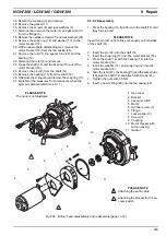
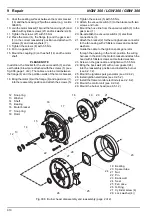
Fig. 908 Burner head, disassembly and reassembly (page 2 of 2)
21
20
19
18
17
16
15
14
13
12
22
25
24
23
26
27
28
12 Snap ring
13 Washer
14 Shaft
15 Bearing
16 Motor bracket
17 Snap ring
18 Rotor
19 Bearing
20 Spacer tube
21 Nut
22 Pin
23 Back wall
24 Seal
25 Fan case
26 O-Ring
27 Cylinder screw (4)
28 Lock washer (4))

