background image


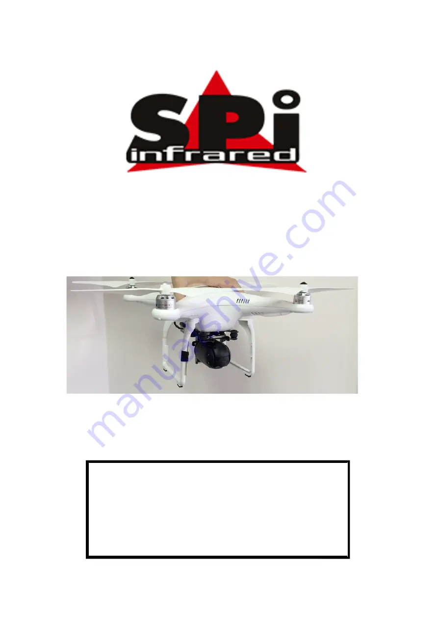
Phantom 2 M2-D 


Configuration 


Ver 1.0 


This  document  is  the  property  of  Sierra  Pacific  Innovations  Corp  (“SPI 
Corp”).  SPI Corp reserves all rights to this document, data, invention, and 
content herein described. This document is confidential, including the fact 
of its existence and is not to be disclosed, in whole or in part, to any other 
party and it shall not be duplicated, used, transmitted or copied in any form 
without  the  express  prior  written  permission  of  SPI  Corp.  Acceptance  of 
this document will be construed as acceptance of the foregoing conditions.

Summary of Contents for Phantom 2 M2-D

Page 1: ...nd content herein described This document is confidential including the fact of its existence and is not to be disclosed in whole or in part to any other party and it shall not be duplicated used transmitted or copied in any form without the express prior written permission of SPI Corp Acceptance of this document will be construed as acceptance of the foregoing conditions ...

Page 2: ... product are subject to change without notice SPI Corp reserves the right to make changes without notice in the specifications and materials contained herein and shall not be responsible for any damages including consequential caused by reliance on the materials presented including but not limited to typographical and other errors relating to the publication For Further information please contact ...

Page 3: ...sg Configuration 7 4 LightBridge Configuration Calibratrion 14 5 M2 D SBUS Adapter Configuration Calibration 17 6 System Test 30 6 1 Testing Return to Home Function 30 6 2 Communication Disconnect Testing 30 6 3 Camera Pitch Testing 31 6 4 Day IR NUC Polarity 31 6 5 Zoom In Out 32 6 6 Bypass Single Yaw 33 6 7 Motor on off 34 7 Operation 3 ...

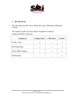
Page 4: ...troduction The document describes the configuration and calibration of Phantom 2 M2 D The following table describes which component should be configured and or calibrated Component Configuration Calibration Section Futaba t14sg 3 DJI Lightbridge 4 M2 D SBUS Adapter 5 DJI Phantom 6 ...

Page 5: ...ers before any configuration calibration activity During configuration and or calibration activity propellers should be removed The propellers can be re assembled at the end of the configuration calibration activity The cover of the Phantom 2 should be removed to allow access to the SBUS adapter USB port ...

Page 6: ... is factory configured to 8 channels by default The first step would be to enable 12 channels support 3 1 Setting 12 Channels Support Mode The following image defines the control 12 channels in Futaba t14sg a Double click on System key b Go to TRAINER and press RTN key c Go to last screen and chose the 12 channels option ...

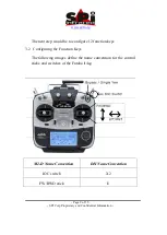
Page 7: ...rmation The next step would be to configure 12 function keys 3 2 Configuring the Function Keys The following images define the name convention for the control sticks and switches of the Futaba t14sg M2 D Name Convention DJI Name Convention IOC switch X2 FW BWD stick E ...

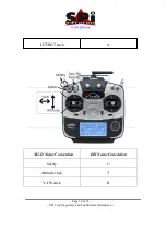
Page 8: ...www x20 org Page 10 of 35 SPI Corp Proprietary and Confidential Information LFT RGT stick A M2 D Name Convention DJI Name Convention Safety U Altitude stick T YAW stick R ...

Page 9: ...www x20 org Page 10 of 35 SPI Corp Proprietary and Confidential Information ...

Page 10: ...org Page 11 of 35 SPI Corp Proprietary and Confidential Information The following images describes the name convention for sticks and switches movement Following the following steps to define the function keys ...

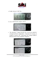
Page 11: ... Double click on LNK Key b Go to FUNCTION and press RTN c The following 3 images describe the 10 keys that should be configured and their configuration Following the 3 images an example of one key SE is provided The example should be followed and all 10 keys should be configured ...

Page 12: ...www x20 org Page 13 of 35 SPI Corp Proprietary and Confidential Information For Example Config the SE key to channel 6 a Go to Channel 6 and press RTN b Select the key SE and press RTN ...

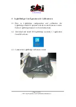
Page 13: ...bratrion 4 1 Prior to Lightbridge configuration and calibration the Lightbridge should be updated with the recent firmware version Follow Lightbridge manual web site instructions 4 2 Download and install DJI Lightbridge Assistant_1 3 application from DJI web site 4 3 Connect the LightBridge to Remote control ...

Page 14: ...prietary and Confidential Information 4 4 Connect the LightBridge Ground system to Your PC using micro USB 4 5 Execute LightBridge Application Update last version of ground and Air systems set channels from 1 to 16 and press calibration key ...

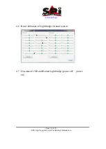
Page 15: ...www x20 org Page 16 of 35 SPI Corp Proprietary and Confidential Information 4 6 Run Calibration of Lightbridge Ground system 4 7 Disconnect USB and Restart Lightbridge power off power on ...

Page 16: ...rp Proprietary and Confidential Information 5 M2 D SBUS Adapter Configuration Calibration 5 1 Download and install M2 D S Bus Adapter Config and DJI Phantom 2 applications 5 2 Connect the M2 D S Bus Adapter to Your PC using micro USB ...

Page 17: ...www x20 org Page 18 of 35 SPI Corp Proprietary and Confidential Information 5 3 Execute M2 D S Bus Adapter Config application ...

Page 18: ...on 5 4 Configuration Channels and Camera mode of M2 D S Bus Adapter Note Camera Day IR NUC is set to channel 12 while at the Futaba the Day IR NUC is set to channel 11 The reason is a bug in the Lightbridge which maps channel 11 from the Futaba to channel 12 to SBUS Adapter ...

Page 19: ...alibration of SBUS Adapter includes two steps a The Bypass Single Yaw switch in the Futaba should be set to Bypass mode forward like in the following image Switch to the Calibration tab in the SBUS Adapter Config App Press Start button in the Calibration Tab and move the sticks of the Futaba to full range for 5 seconds ...

Page 20: ...www x20 org Page 21 of 35 SPI Corp Proprietary and Confidential Information and press Finish button ...

Page 21: ...www x20 org Page 22 of 35 SPI Corp Proprietary and Confidential Information Connect the DJI Phantom 2 to Your PC using micro USB and execute Phantom 2 application Switch to RC tab in Basic menu ...

Page 22: ... Information Set the Phantom 2 application to NAZA Mode by pressing the Naza M button at the top of the application Check direction of sticks Move each stick to 4 directions and verify that the move of the stick is replicated correctly in the Phantom 2 application ...

Page 23: ...ch down and verify that the Control Mode Switch indication in Phantom 2 application points to FailSafe Move the Safety switch to center and verify that the Control Mode Switch indication in Phantom 2 application points to Atti Move the Safety switch up and verify that the Control Mode Switch indication in Phantom 2 application points to GPS Safety Switch Position Required Control Mode Switch indic...

Page 24: ...r Atti Up GPS In case that the indicated Control Mode Switch does not match the table the range of the Futaba key should be set Setting of Futaba range is described in the following steps a Double click on LNK Key b Go to END POINT and press RTN c Change Range of the current channel ...

Page 25: ...www x20 org Page 26 of 35 SPI Corp Proprietary and Confidential Information Calibration Press START button DJI Application Press Cal with DJI S Bus Adapter Config App ...

Page 26: ...www x20 org Page 27 of 35 SPI Corp Proprietary and Confidential Information Wait 5 seconds and Press Cal with DJI button again Press FINISH button DJI Application ...

Page 27: ...ck Channel Max left Center Max Right LFT RGT A 1000 0 1000 YAW R 1000 0 1000 Stick Channel Max Backward Center Max Forward FW BWD E 1000 0 1000 Altitude T 1000 0 1000 Move the Safety switch down and verify that the U Channel monitor displays a value greater than 750 Move the Safety switch to center and verify that the U Channel monitor displays a value greater than 50 and lower than 50 Move the Sa...

Page 28: ... Information 5 7 Close all applications 5 8 Disconnect all USB cables 5 9 Power off the Phantom 2 and the Lightbridge 5 10 Re assemble Phantom 2 covers Do not re assemble Phantom 2 propellers 5 11 Power on Phantom 2 and Lightbridge and continue with system testing ...

Page 29: ...y switch to Return to Home position down and verify that the 2 LEDs of Phantom 2 are blinking in red green colors Move the Safety key to Normal position up and verify that the two LEDs of the Phantom 2 are blinking in yellow colors 6 2 Communication Disconnect Testing Before starting the test verify that the LED of the Phantom 2 is blinking in red green colors Disconnect the Futaba remote control ...

Page 30: ...rd and verify that the camera is in day mode by observing the video Move the Day IR NUC Polarity switch to center and verify that the camera is in IR mode by observing the video Move the Day IR NUC Polarity switch backward and return to center within 1 second and verify that the camera polarity is changed by observing the video Repeat this action for several times to verify that the camera switche...

Page 31: ...mera is performing NUC operation by observing the camera pitch changes and look down 6 5 Zoom In Out Move the Zoom switch forward and verify that camera is zooming in by observing the video Move the Zoom switch to center and verify that the zoom camera does not change by observing the video Move the Zoom switch backward and verify that the camera is zooming out by observing the video ...

Page 32: ... enter the image from the right side When moving the stick to the right a black area should enter the image from the left side Move the Bypass Single Yaw switch forward i e setting Bypass mode Continuously move the left stick to the left and to the right i e generating YAW command and verify that the image of the camera does not change by observing the video Move the Bypass Single Yaw switch to th...

Page 33: ... same time move the right stick to left backward position and the left stick to right backward position and verify that the 4 motors start Following that At the same time move the right stick to left backward position and the left stick to right backward position and verify that the 4 motors are off ...

Page 34: ...dy for first fly While in Single Yaw mode the sensitivity of the YAW control changes dynamically As a result when taking off and recovering the system must be in Bypass mode The Bypass mode is entered by moving the Bypass Single Yaw switch forward During flight it is recommended to switch the mode to Single Yaw and use the special benefits of smooth camera operation while in this special mode ...

Reviews: