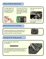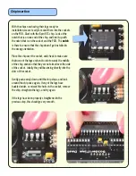
With the chips now having their legs ready for
installation, we are ready to mount them into the sockets
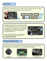
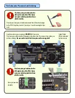
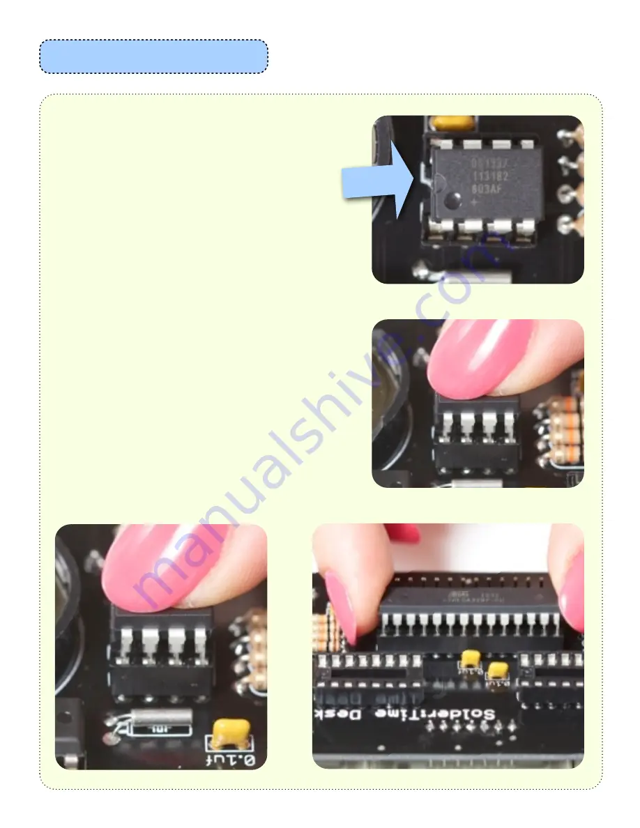
on the PCB. Start with the 8 pin RTC chip. Look at the
notch that is on one end of the chip, and line it up with
the notch that is on the socket, and the PCB. The
notch
is there to ensure that the chip doesn’t get installed in
the wrong orientation.
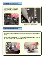
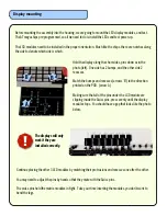
Place the chip over the socket, and check to make sure
that none of the legs are bent too far towards the middle
of the chip, and also that they are not aimed over the side
of the socket. Ideally they will be aiming directly into the
slots of the socket.
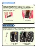
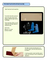
Gently push evenly down until the chip stops, and look
around the chip once again. If any of the legs have
buckled under, or missed the holes in the socket, remove
the ship, straighten the legs, and try again.
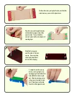
If the legs have been properly straightened in the
previous step, this should go very smooth.
Chip insertion


