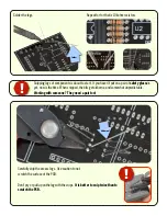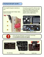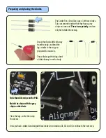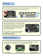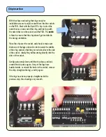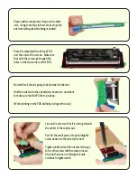
Before mounting the assembly into the housing, we are going to mount the LED display modules, and test.
The ATmega ships pre-programmed, so all we need to do is install the LEDs and test power up.
The LCD modules need to be installed in the proper orientation. Much like the chips, there are notches along
the side to denote which side is which.
Display mounting
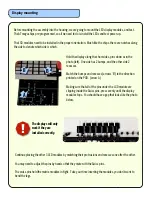
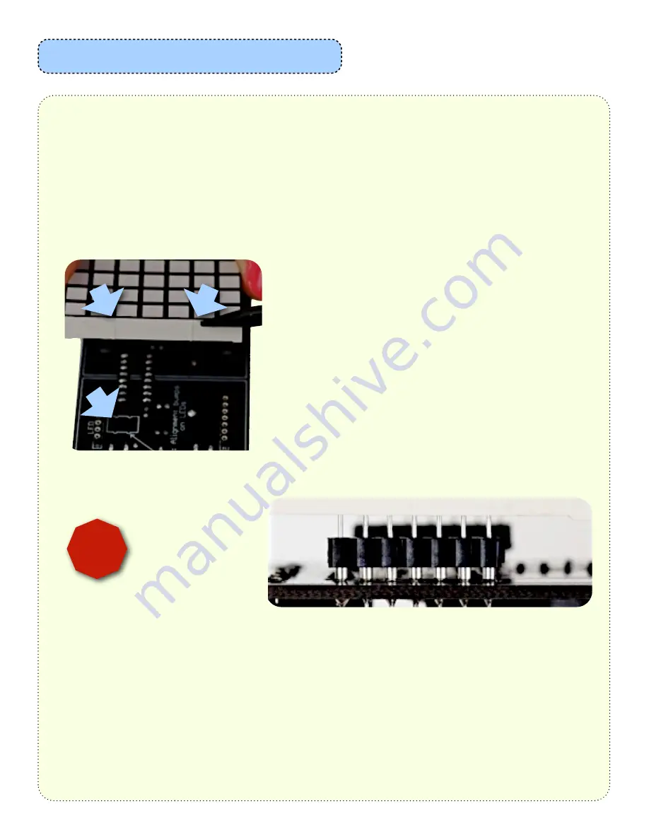
Hold the display along the short sides, pins down as in the
photo (left). One side has 2 bumps, and the other side 2
recesses.
Match the bumps and recesses (arrows ‘B’) to the direction
printed on the PCB. (arrow A)
Making sure that all of the pins under the LCD module are
slipping inside the Swiss pins, press evenly until the display
module stops. You should have a gap that looks like the photo
below.
A
B
B
The displays will only
work if they are
installed correctly.
!
Continue placing the other 3 LED modules by matching their protrusions and recesses one after the other.
You may need to adjust the pins by hand so that they mate with the Swiss pins.
The swiss pins hold the matrix modules in tight. Take your time inserting the modules, you don’t want to
bend the legs.


