background image

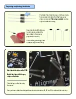
Preparing and placing the diodes

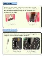
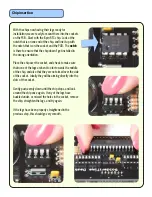
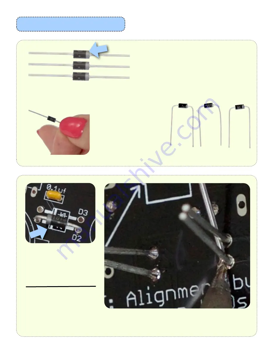
The Solder Time Desk Clock uses 3 of these diodes.
Take a moment to notice that they have a grey 
stripe one one end.  

These have polarity

, and can 

only be installed in one way.

Grasp the diode a little bit away 
from the body, and bend the 
legs similar to the way you 
prepared the resistors.

These diodes get their legs bent 
a little bit away from the body.  

Note the white stripe on the PCB.

Match the stripe with the grey
stripe on the diode

Flare the legs, solder then snip 
the excess.

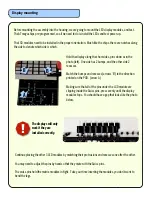
Once you have soldered and snipped these diodes into locations D1, D2, and D3, continue to the next step.

Summary of Contents for Solder Time Desk Clock

Page 1: ...y kit to build however there are certain steps that need to precede other steps Read through the entire guide and check your parts Questions or problems let us know at support spikenzielabs com Unpack...

Page 2: ...PCB The value for the required resistor is printed on the PCB to reduce mistakes Preparing a 100 ohm resistor Placing and soldering the resistors Start with the single 100 ohm resistor It gets placed...

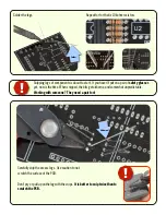
Page 3: ...f the PCB Snipping legs of components is about to start If you haven t put on a pair of safety glasses yet now is the time When snipped the bits get airborne and somewhat unpredictable Working with so...

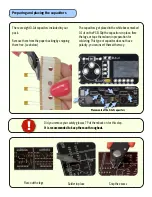
Page 4: ...boxes marked 0 1 uf on the PCB Slip the capacitors in place flare the legs or tape them down in preparation for soldering This type of capacitor does not have polarity you can insert them either way...

Page 5: ...Grasp the diode a little bit away from the body and bend the legs similar to the way you prepared the resistors These diodes get their legs bent a little bit away from the body Note the white stripe o...

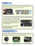
Page 6: ...through and the socket is laying as flat as possible on the PCB If it s uneven reheat the first and last legs while pressing the socket into place Once you re happy with how it looks continue solderin...

Page 7: ...he metal base of the regulator The Solder Time Desk Clock uses a standard CR2032 cell as a backup for the time Match the outline of the battery holder placement on your PCB secure and solder in place...

Page 8: ...matrix side of the PCB Make sure your soldering matches these photos exactly Swiss pin inserted properly Apply Solder Where indicated by blue arrows This kit uses Swiss pins to hold and connect the L...

Page 9: ...s Repeat for the other button Place the DC barrel jack as in the photos below left Hold it in place with a piece of tape and solder one of the three legs Make sure it is perfectly flat against the PCB...

Page 10: ...n the ends press evenly against a flat surface Perfectly perpendicular Legs are square to the body Do this to each of the five chips The crystal is a small thin metal barrel the legs are very thin Pla...

Page 11: ...the chip over the socket and check to make sure that none of the legs are bent too far towards the middle of the chip and also that they are not aimed over the side of the socket Ideally they will be...

Page 12: ...ther side 2 recesses Match the bumps and recesses arrows B to the direction printed on the PCB arrow A Making sure that all of the pins under the LCD module are slipping inside the Swiss pins press ev...

Page 13: ...ke sure you are installing it with the writing up As in the photo right Backup battery installation Connect a 9 12v DC power source to the DC barrel jack You should see the LED display light up Press...

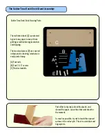
Page 14: ...e exposed surface of the red acrylic This is to avoid dust and fingerprints Solder Time Desk Clock Housing Parts The red tinted sheet C is protected by peel away paper to keep it from getting scratche...

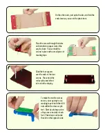
Page 15: ...in place with a small piece of masking tape Slide the four spacers over the ends of the four screws These hold the red acrylic panel offset in front of the display To make the next few steps easier yo...

Page 16: ...is going to be fastened to the feet Hold the side foot in the orientation shown here and check to make sure that the PCB is top side up White printing on the PCB will help you figure this out Line up...

Page 17: ...red acrylic sheet Peel and discard the acrylic protective coverings Remove the masking tape as well as the plastic protective sheeting from the feet Peel away the paper protective covering from the fr...

Page 18: ...nzielabs com is the place to get help Click here to learn about how to use the clock Clock instructions For comments other than support related inquiries please email feedback spikenzielabs com we wou...

Reviews: