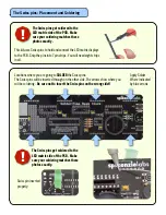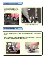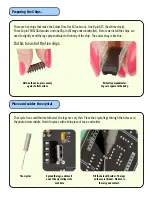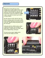
Placing and soldering voltage regulator
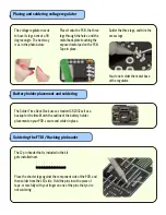
The voltage regulator needs
to have its legs bent at a 90
degree angle. The best way
is as in the photo below:
Place it onto the PCB, the three
legs through the holes, and the
metal back plate touching the
exposed metal pad on the PCB.
Tape in place.
Solder the three legs, and trim the
excess legs.
You do not solder the metal base
of the regulator.
The Solder Time Desk Clock uses a standard CR2032 cell as a
backup for the time.Match the outline of the battery holder
placement on your PCB, secure and solder in place.
Battery holder placement and soldering
The 12 pin header that is included in the kit
gets installed next.
Soldering the FTDI / Hacking pin header
Place the shorter legs against the component side of the PCB, and
then solder from the LED side. Hold the pins in with a piece of
tape, or carefully with your finger on one of the pins that you’re
not soldering.


