background image

SPILSBURY 

COMMUNICATIONS 

1495 Franklin Street 

Vancouver, B.C. V5L 5B6 

Tel: (604) 254-6411 

Fax: (604) 254-2080 

Telex: 04-55482 


SERVICE MANUAL


SBX-11A 


SSB Portable 

Radio Telephone 


65-5014 


September, 1997 

Summary of Contents for SBX-11A

Page 1: ...SPILSBURY COMMUNICATIONS 1495 Franklin Street Vancouver B C V5L 5B6 Tel 604 254 6411 Fax 604 254 2080 Telex 04 55482 SERVICE MANUAL SBX 11A SSB Portable Radio Telephone 65 5014 September 1997 ...

Page 2: ...ble Whip V CIRCUIT DESCRIPTION A Oscillators B Receiver C Transmitter D Metering E Miscellaneous Circuitry VI TUNING ALIGNMENT A Crystal Information B Channel Filter Information C Main Chassis Removal D Tuning to Channel Frequency E Basic Tuning VII MAINTENANCE REPAIR A Trouble Shooting B Stage Gain Charts C Replacement of PA VIII PARTS LIST SCHEMATICS TOP AND BOTTOM VIEWS OF PRINTED CIRCUIT BOARD...

Page 3: ...rophone are accommodated on the front panel A cover with carrying handle is supplied to protect the entire front panel when the set is not being operated or when in transit Internal circuitry is of the utmost simplicity employing silicon type transistors and the latest silicon integrated circuits Plug in tuning coils numerous test jacks and simple circuit board design ensure easy tuning and mainte...

Page 4: ...Range 1 6 8 MHz Battery Drain Receiver 30 mA average Transmit 600 mA average Batteries 9 size D flashlight cells See Section III Dimensions overall Height 8 6 cm 3 3 8 Width 22 9 cm 9 Length 32 4 cm 12 3 4 Weight with Batteries 3 6 kg 8 lbs 2 Transmitter Power Output 5 10 Watts PEP depending on battery condition D O C rating 8 7 Watts PEP at 11 75 Volts Spurious Output Maximum 43 dB below PEP Carr...

Page 5: ... 3 Receiver Sensitivity 0 5 uV for 12 dB SINAD Selectivity 2 1 kHz bandwidth at 6 dB down 4 5 kHz bandwidth at 60 dB down AGC Input variation from 5 uV to 100 mV produces less than 10 dB output change Image and Spurious Rejection 44 dB or better Clarifier Range Nominally 0 003 of channel frequency AF Response Same as for transmitter AF Output 250 mW to speaker at 5 distortion ...

Page 6: ...ntenna is of the tuneable type it must be tuned to the channel frequency selected Each time a different channel is selected by the CHANNEL switch the antenna must be retuned to the new frequency 8 To tune the antenna use the following procedure a Select the desired channel b Press the TUNE button while quickly tuning the antenna for maximum POWER OUTPUT indication on the metre IMPORTANT When tunin...

Page 7: ...tion to 22 Deg F is required a nickel cadmium battery will be needed The temperature range of the various battery types are Nickel Cadmium 22 Deg F to 122 Deg F 30 Deg C to 50 Deg C Alkaline 14 Deg F to 122 Deg F 10 Deg C to 50 Deg C Zinc Carbon 32 Deg F to 122 Deg F 0 Deg C to 50 Deg C If the above is not a consideration then the choice may depend on whether rechargeable or non rechargeable types...

Page 8: ...mmended Battery Life Hrs No of Recharges SCL Eveready Burgess Mallory Nickel Cad 50 300 AC 19K CH4 CD 10 Alkaline 50 0 AC 19I E95 AL 2 MN 1300 NOTE The SCL number listed above is a complete battery set When ordering by manufacturer s number nine are required ...

Page 9: ...his region while recharging NOTES a New or fully charged batteries may start operation in the C section of the meter this condition may be ignored as they will quickly discharge to the B or green working section of the scale b No accurate estimate of the power remaining in the nickel cadmium batteries can be made by reading the meter scale Charging should be based on the hours of use generally 2 2...

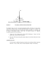
Page 10: ...n but serve only as a static discharge path 3 The dipole may be supported from any convenient objects such as poles trees buildings etc 4 The maximum signal is received and transmitted broadside to the antenna 5 The length L of each 1 2 of the antenna is L 234 freq MHz of channel preferably the antenna height H length L 6 TO OPERATE Set up antenna and connect leads to the SBX 11A one to each bindi...

Page 11: ...ise may be needed if the ground is poor Some notes for tuneable antennas i e Spilsbury Communications Ltd STA 210 Series are 1 Connect wire from resonator unit to antenna ANT binding post Connect wire from ground stake to ground GND binding post 2 Press the TUNE button and quickly adjust antenna for maximum indication on front panel metre ADDITIONAL NOTE It will be noticed on different frequencies...

Page 12: ...T emitter follower couples the signal from the receiver input filter to the mixer U101 In U101 the signal is amplified and mixed with the channel oscillator frequency producing the I F frequency which is fed to U102 through T101 2 The signal is further amplified by U102 then passes through transformer T102 and sideband filter FL101 3 U103 which has two outputs pin 6 and 8 amplifies the signal from...

Page 13: ...er FL103 through T R switch diode D108 D102 is biased off 5 The channel oscillator frequency H F O from Q106 is also fed into the balanced mixer FL103 and the two main output frequencies are the channel oscillator frequency the I F frequency 6 The transmitter filter TX is tuned to select the lower of these two frequencies which is an upper sideband signal and reject all other frequencies 7 The des...

Page 14: ...it to prevent feedback from the speaker to the microphone during the switching interval 2 Operate Tune Switch When in tune position a DC current is passed through double balanced mixer FL102 unbalancing it and permitting the LFO frequency to pass through it through Diodes D101 and D102 turned on by the Tune Button into the 2nd double balanced mixer FL103 The LFO input to FL103 produces the suppres...

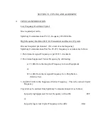
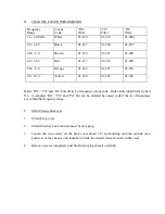
Page 15: ... is calculated as follows 1 Determine Assigned Frequency as per D O C document 2 Determine Suppressed Carrier Frequency by subtracting a 1 5 kHz from the Assigned Frequency for Land Equipment or b 1 4 kHz from the Assigned Frequency for a Ship Station Marine Use 3 Add 456 5 kHz to the Suppressed Carrier Frequency This is the Actual Crystal Frequency Crystals may be ordered from Spilsbury Communica...

Page 16: ...and PA Filter Kits by frequency colour code Order individual filters by Part No A complete RX TX and PA Kit can be ordered by colour code if the two frequencies are within the frequency range C Main Chassis Removal 1 Unlatch top cover 2 Unlatch battery box and disconnect battery plug 3 Loosen the two screws on the back cover about 1 8 and holding onto the outside case push rear of the chassis with...

Page 17: ...ts a Remove crystal clamp and P A tank coil cover can b Install TX and RX crystals in the desired channel positions c Install TX filters and RX filters in the desired channel positions The filters are marked on the pin side with T and R and an arrow which corresponds to the arrows on the printed circuit board d Install P A tank coils in the desired channel positions Note the coloured stripe on the...

Page 18: ...pling capacitor e Press the P T T button on the microphone and adjust the TX crystal trimmer screw of the channel being tuned until the TX crystals are on their correct frequencies 4 Receiver Tuning to Channel Frequencies a Connect the signal generator to the ANT GND terminals and the audio metre across the speaker terminals b Inject an unmodulated R F signal of the channel frequency desired at a ...

Page 19: ...minals b Press the TUNE button while making the following adjustments c Tune the slugs of the transmitter channel filter being tuned from the all out position slugs flush with top of coil can until the R F ammeter begins to indicate A sensitive oscilloscope or an R F VTVM connected across the load will give a better initial indication It is best to alternately tune each coil of the coil of the fil...

Page 20: ...er frequencies If the peak is not quite reached at minimum capacity remove the coil can cover and remove from the appropriate tank coil the appropriate capacitor connected to the pins on either side of the coloured strip on the base of the coil Do not remove unless necessary f Loosely couple a counter to the R F output and check that the transmitter output frequency is equal to the crystal frequen...

Page 21: ... to approximately 455 kHz and increase until a 1000 Hz beat note is heard Tune T101 T102 and T103 for maximum audio output Final signal level should be similar to level given in RX stage gain chart 3 Transmitter a PA Bias R153 Measure supply current Turn R153 fully counter clockwise Advance F153 for increase of about 5 mA 4 mA to 7 mA while pushing the P T T switch but without modulation b TX Gain...

Page 22: ... c d and e of Transmitter tuning to channel frequencies but disregard detuning instructions v Set R159 for 0 3A output into the dummy load resistor c ALC R144 With set up as above double audio input voltage to MIC jack 6 dB increase and adjust R144 for 0 3A into the dummy load resistor d Carrier Insertion R137 R137 must be set after R159 Step B i Remove audio input at MIC jack ii Push the TUNE but...

Page 23: ...know the batteries are new or in good charged condition open the battery case and 5 Check the polarity of each battery refer to diagram in battery case 6 Check the fuse and replace with spare if necessary 7 Make certain that the battery plug is fully engaged NOTE If the battery voltage is low with good batteries the temperature may be too low for the battery type in use See battery section If the ...

Page 24: ...input Transmitter tuned to average gain channel with 0 3A R F into 50 Ohm TEST POINT VOLTAGE REMARKS MIC test jack TP110 4 6 mV RMS This level adjusted to result in correct voltage at AUD test point AUD test jack TP109 45 mV RMS 1000 Hz Audio IF 2 test jack TP103 120 mV P P Scope measurement only DSB minus carrier Two Tone Pattern Junction D108 Input of FL103 100 mV RMS Junction R159 FL 103 70 mV ...

Page 25: ...ls should be adjusted for 2 4 V RMS across the speaker or 30 Ohm load 250 mW TEST POINT INPUT LEVEL RMS INPUT FREQUENCY ANT binding post RX H F O TP101 1st IF TP102 2nd IF TP103 Audio TP109 1 uV 1 uV 20 uV 18 mV 3 6 mV Channel Frequency 455 5 kHz 455 5 kHz 455 5 kHz 1000 Hz 3 Oscillators Oscillator levels are given on the schematic C REPLACEMENT OF PA The PA module LPA2 SCL 67 076 may be replaced ...

Page 26: ...olding C127 support bracket If present e Remove three screws S under PCB and remove PA module 2 Installation of Module LPA2 a Feed leads of T105 T106 and L108 through holes in PCB outside twisted pair on T106 goes through centre hole of 3 b Replace 3 screws and solder above leads c Solder inside twisted pair on T106 and lead of R149 to feed through pin inside module d Replace C52 support bracket e...

Page 27: ...rease of about 5 mA 4 mA to 7 mA b Operate transmitter into dummy lead following section VI D5 of the manual If antenna current falls within 220 to 360 mA RF retune as described in manual c If required antenna current cannot be achieved follow Section VI E3 except instead of step a in that section substitute step a immediately above Then tune the transmitter again ...

Page 28: ...Ch Blank 59 082 Plastic Cover 57 1138 FUSE F1 2A FB 43 030 Fuseholder 53 009 HANDLE Handle Plastic 45 181A End Cap two required 45 181B KNOBS Channel Selector 28 044 Volume Clarifier 28 087 LOUDSPKR LS1 30 Ohms 2 3 4 Ins 23 011 METALWORK Front Panel 57 1676 Lid 57 1682A Main Case 57 1681A Battery Box no inserts 57 1674A METRE M1 500uA 400 Ohms 31 027 MICROPHONE Complete Assembly 32 026 RESISTOR R1...

Page 29: ...MBLY Cont d SOCKETS J1 3 Pin DIN Battery 22 113 Antenna Red 13749 001 Ground Black 30 051 SWITCHES S1 Part of R1 S2 Tune Operate 4PDT Switch Assy 36 088 Bezel for S2 36 093 Button for SW 36 156 Switch for SW 36 204 ...

Page 30: ...SECTION VIII PARTS LIST BATTERY BOX REF DESCRIPTION PART NO CONTACT Kit Two pieces 62 169 PAD Rubber 21 105 PLUG P1 3 Pin DIN 34 062 TUBES Plastic three required 21 046 ...

Page 31: ...0V 24 259 C115 Ceramic Disc 0 001uF 10 100V 24 044 C116 Mica DM10 100pF 5 500V 15 040 C117 Metalized Foil 0 1uF 10 250V 24 159 C118 Metalized Foil 0 1uF 10 250V 24 159 C119 Electrolytic 1uF 15V 19 164 C120 Metalized Foil 0 1uF 10 250V 24 159 C121 Ceramic Disc 0 01uF GMV 100V 24 025 C122 Ceramic Disc 0 01uF GMV 100V 24 025 C123 Ceramic Disc 0 003uF 10 100V 24 175 C124 Electrolytic 10uF 15V 19 083 C...

Page 32: ...9 1000pF 15 051 C153 Electrolytic 100uF 25V 19 115 C154 Ceramic Disc 0 01uF 10 100V 24 361 C155 Ceramic Disc 0 01uF 10 100V 24 361 C156 Metalized Foil 0 1uF 10 250V 24 159 C157 Ceramic Disc 0 01uF 10 100V 24 361 C158 Ceramic Disc 0 01uF 10 100V 24 361 C159 Metalized Foil 0 1uF 10 250V 24 159 C160 Electrolytic 10uF 15V 19 083 C161 Electrolytic 10uF 15V 19 083 C162 Ceramic Disc 0 01uF 10 100V 24 361...

Page 33: ...con 1N459A 71 0459 D102 Silicon 1N459A 71 0459 D103 Silicon 1N459A 71 0459 D104 Silicon 1N459A 71 0459 D105 Silicon 1N459A 71 0459 D106 Silicon 1N459A 71 0459 D107 Silicon 1N459A 71 0459 D108 Silicon 1N459A 71 0459 D109 Silicon 1N459A 71 0459 D110 Zener 1N5239B 71 5239 D111 Silicon 1N459A 71 0459 D112 Silicon 1N459A 71 0459 D113 Germanium 1N67A 71 1067 D114 Silicon 1N459A 71 0459 D115 Germanium 1N...

Page 34: ... 1 4W 10K 5 14 008 R105 Carbon Film 1 4W 10K 5 14 008 R106 Carbon Film 1 4W 10K 5 14 008 R107 Carbon Film 1 4W 100 Ohm 5 14 002 R108 Carbon Film 1 4W 470 Ohm 5 14 050 R109 Carbon Film 1 4W 82 Ohm 5 14 093 R110 Carbon Film 1 4W 10K 5 14 008 R111 Carbon Film 1 4W 10K 5 14 008 R112 Carbon Film 1 4W 47 Ohm 5 14 056 R113 Carbon Film 1 4W 22K 5 14 010 R114 Carbon Film 1 4W 1K 5 14 005 R115 Carbon Film 2...

Page 35: ...K 20 13 083 R141 Carbon Film 8 2K 5 14 082 R142 Carbon Film 180 Ohm 5 14 037 R143 Carbon Film 1 4W 10K 5 14 008 R144 Variable Carbon 1 10W 10K 20 13 083 R145 Carbon Film 100K 5 14 013 R146 Carbon Film 3 3M 5 14 020 R147 Carbon Film 330 Ohm 5 14 040 R148 Carbon Film 20 Ohm 5 14 076 R149 Carbon Film 12 Ohm 5 14 001 R150 Thermistor 33 Ohm 09 134 R151 Carbon Film 330 Ohm 5 14 040 R152 Carbon Film 220 ...

Page 36: ... 5 14 010 TRANSFORMERS T101 455 kHz I F 01 155 T102 455 kHz I F 01 155 T103 455 kHz 8K 70 Ohm I F 01 200 T104 ALC Transformer 01 213 T105 P A Output 01 212 T106 P A Input 01 211 TRANSISTORS Q101 Si NCh JFET GP 72 5457 Q102 Si PCh JFET GP 72 5462 Q103 Si NPN GP 72 4124 Q104 Si NCh JFET HF 72 5486 Q105 Si NPN GP 72 4124 Q106 Si NCh JFET HF 72 5486 Q107 Si NCh JFET HF 72 5486 Q108 Si NPN GP 72 4124 Q...

Page 37: ...CAPACITORS C501 Air Variable 1 4 14pF Clarifier 18 031 C502 Film Variable 2 18 5pF 17 037 C503 Film Variable 2 18 5pF 17 037 C504 Mica Variable 390 1400pF 17 031 PLATE Coil and Crystal Grounding 57 1346 SWITCH S501 Sections A to E 40 163 S501 Index 40 125 Four per channel ...

Page 38: ... 1 2 40 128 Spacer Ceramic 2 x 1 4 40 129 Wafer Switch 40 163 Handle Black 45 181A Endcap for 45 181A Handle 45 181B Battery Block 45 312 Catch c w wire for battery box 45 175 Catch less wire for lid 45 176 Clip Crystal 50 093 Socket PCB Jack 50 137 Spring Battery Holder 50 233 Grommet PVC 5 16 51 013 Guide Plate for Centre Case 57 1197 Rail Centre 57 1679 Decal Spilsbury C L Logo 59 018 Decal SBX...

Page 39: ...el Coil 59 145 Decal SBX 11A 59 239 Slug Iron RX TX Coils 00 098 Slug Iron PA Coil 00 105 Button Black for 36 088 Switch 36 156 Microphone Assembly 32 026 Grill Cloth finished 45 184 Fibre Pad Cross Thick 50 150 Coupling Brass For Clarifier Shaft 52 173 Frequency Chart Cover 57 1138 Cover PA Coil 57 1186 Chassis U Frame 57 2258 Rod for Clarifier Control 57 2250 ...

Page 40: ... TITLE Title to the Products shall remain with the Company as security for the purchase price until payment in full is received The Company may obtain possession of the goods by any lawful means should the Customer fail to pay the purchase price when due 12 DAMAGES OR LOSS IN TRANSIT The Company accepts no liability for loss or damage in transit 13 FORWARDING INSTRUCTIONS Forwarding instructions w...

Page 41: ......

Page 42: ......

Page 43: ......

Reviews: