background image

|   

         © 2017

ONIX Installation Manual  |

3

4

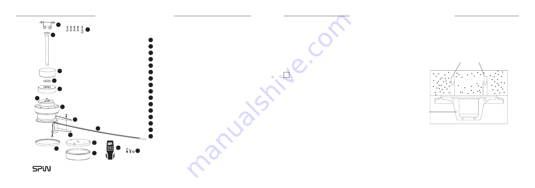
SUPPLIED PARTS

SUPPLIED PARTS

A

B

A

B
C

D

E
F

G

H

I
J

K

L

M
N

O

P

C

D

E

F

G

H

I

J

K

L

M

N

O

P

Mounting Bracket
Expansion Screw (x4) and “J” Hook (x1)
Downrod (Rod Ball, Down Rod, Cross Pin, Cotter Pin)
Ceiling Canopy
Canopy Screw Cover
Coupling Cover
Receiver
Motor
Blade Cover Set
Blade (Length variations based on model)
Blade Holder Set
Base Plate
LED Light Panel (Optional)
LED Light Cap (Optional)
Remote
Bag of Screws

INSTALLATION STEPS

INSTALLATION STEPS

1. MOUNTING BRACKET INSTALLATION

Secure the Mounting Bracket to the concrete ceiling with 

the 4 expansion screws included. 

  !    

NOTE: After securing the mounting bracket, please ensure


   that it is able to bear a minimum tension of 30kg to  


   make sure it’s safe for operation.

Expansion Screws x4 (Front & Back)

Concrete Ceiling

Mounting Bracket

Speed

Timer

h

Speed

Light

Summary of Contents for ONIX SP933

Page 1: ...INSTALLATION MANUAL SP960 SP972 SP984 SP933 SP984AL O N I X ...

Page 2: ...hasing SPIN ceiling fans Please take some time to register your product with us by mailing in the warranty card or register online at www spinfans com sg C CONTENTS ONTENTS Precautions Wiring Supplied Parts Pairing of Remote Control Troubleshooting Functions SPIN Customer Care Mounting Bracket Installation Attaching the Safety Wire Downrod Assembly Hanging the Fan Installing the Blades Base Plate ...

Page 3: ...ensory or mental capabilities or lack of experience and knowledge unless they have been given supervision or instruction concerning use of the appliance by a person responsible for their safety Children should be supervised to ensure that they do not play with the appliance 6 The fan must be earthed and should be installed with a double pole single throw switch Breaker Switch with minimum 3mm cont...

Page 4: ...th variations based on model Blade Holder Set Base Plate LED Light Panel Optional LED Light Cap Optional Remote Bag of Screws INSTALLATION STEPS INSTALLATION STEPS 1 MOUNTING BRACKET INSTALLATION Secure the Mounting Bracket to the concrete ceiling with the 4 expansion screws included NOTE After securing the mounting bracket please ensure that it is able to bear a minimum tension of 30kg to make su...

Page 5: ...Wire Downrod Rod Expansion Screw with J Hook Expansion Screw with J Hook Electrical Wire Downrod Ceiling Canopy Motor Cover Downrod Rod Cross Pin Screw Screw Enlarged Figure Enlarged Figure Cotter Pin Safety Wire 3 DOWNROD ASSEMBL Y Study the diagram below before you assemble the downrod Insert the downrod through the ceiling canopy and receiver coupling cover Direct the electrical wire through th...

Page 6: ...ownrod and align the groove on the rod ball with the groove on the mounting bracket Mounting Bracket Screws Screws Blade Cover Blade 5 INSTALLING THE BLADES To assemble the blades fasten three screws following the diagram as shown Blade Holder Blade Holder Plate Lug Groove Power L Wire Power L Wire Power N Wire Power N Wire To secure the ready blades onto the blade holder plate fasten the blade ho...

Page 7: ...plate and the light rotate the plate to lock the screws and tighten them Light Cover Light Plate Lug Light Plate Input Light N Orange Wire Output Light L Blue Wire WIRING WIRING Insulating sleeve Current carrying wires Motor shaft Safety cord Earth wire Cross bolt Locking nut Locking pin DC MOTOR LED YELLOW GREEN GROUND CONNECTOR BLOCK BLUE AC IN N AC IN L BROWN BLUE BROWN ORANGE LIGHT BLUE LIGHT ...

Page 8: ...button between 1 hour to 9 hours Press and hold to turn off the timer Pairing of Remote Control Firstly ensure the power supply to the ceiling fan is switched off and the remote is not in use Switch on the power to the ceiling fan you should hear a beep Within 3 seconds press the Power Button to switch on the fan Proceed to press the Timer Button Upon completing these steps you will hear a long be...

Page 9: ...ROPOSED SOLUTION S Check power supply is turned on Check if fan wiring is correct Check if the wiring of the remote control s receiver is correct Check if remote control s batteries are installed properly PROBLEM Unable to control speed and or light PROPOSED SOLUTION S Check if the wiring of the remote control s receiver is correct Check if remote control s batteries are working and installed prop...

Page 10: ...NOTES NOTES ...

Page 11: ...SPIN Pte Ltd 1 Tampines North Drive 1 04 15 T Space S528559 T 6298 1038 F 6298 0780 www spinfans com sg O N I X ...

Reviews: