PulseBlasterDDS
IV. Connecting to the PulseBlasterDDS Board
Connector Information
SMA Connectors labeled DAC_OUT_0, DAC_OUT_1, and DAC_OUT_2
Outputs DDS signals generated by the user’s Program. The output impedance is 50 ohms.
Output power is approximately 10 dBm. Figure 4 is a portion of figure 2 that illustrates which RF output
corresponds to which SMA connector.
Figure 4:
SMA Connectors
DB-25 - TTL Output Signal Bits
Outputs TTL signals generated by the user’s Program. Please consult the table below for bit
assignments.
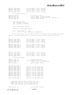
Pin Assignments
Pin#
Bit#
Pin#
Bit#
1
GND
14
GND
2
Reserved
15
Reserved
3
GND
16
Reserved
4
Reserved
17
GND
5
Reserved
18
Reserved
6
GND
19
9
7
8
20
GND
8
7
21
6
9
GND
22
5
10
4
23
GND
11
3
24
2
12
GND
25
1
13
0
Table 3:
Output bits and signals of the PulseBlasterDDS board
9/20/200517
DAC
RF
Outputs
(SMA)
Phase0-15
Gate
DAC
Gate
Phase0-15
Gate
DAC
www.spincore.com
Tx
Rx
DAC_OUT_2
DAC_OUT_0
DAC_OUT_1


