RadioProcessor-G
2017-09-04
16
www.spincore.com
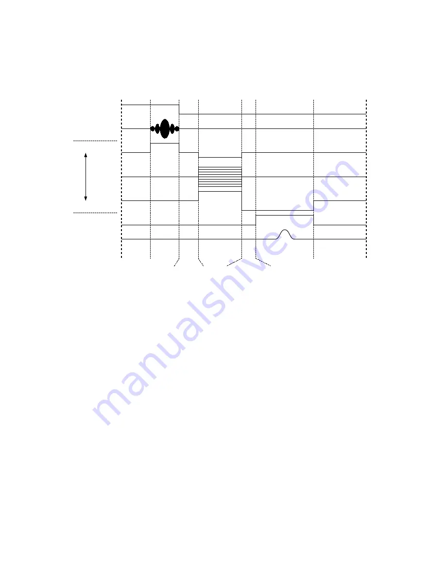
Figure 4:
General timing diagram of the basic gradient echo sequence (not to scale). A single scan is
performed as follows: A de-blanking TTL pulse is applied to allow for RF Power Amplifier warm-up (Blanking Delay),
and then a single RF pulse (hard or shaped) is applied to the sample for a specified amount of time (Pulse Time). At that
same time, the slice gradient is applied for slice selection. The high voltage induced on the sample coil is allowed to ring
down (Transient Time), after which all three gradients are applied (Phase Gradient Time). A period of time is waited to
account for rise time of the gradient amplifiers (Gradient Echo Delay). The readout gradient coils then produce a
gradient echo that is acquired by the RF in of the board (Acquisition Time). The acquisition time is determined by the
number of points and the spectral width. After acquisition, the sample is then allowed to relax for a time (Repetition
Delay). This scan procedure is then repeated for next phase gradient amplitude until all of the data has been acquired.
RF Out
Blanking Bit
Slice
Phase
Readout
Acquisition
RF In
Blanking
Delay
Pulse
Time
Transient
Time
Phase
Gradient Time
Acquisition Time
Repetition Delay
Gradient Echo
Delay
G
ra
di
en
ts


