background image

IM-P344-01 

CTLS Issue 4

1

AEL3 Electric Linear Actuators

3583150/4

(P100018817-B)

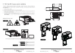
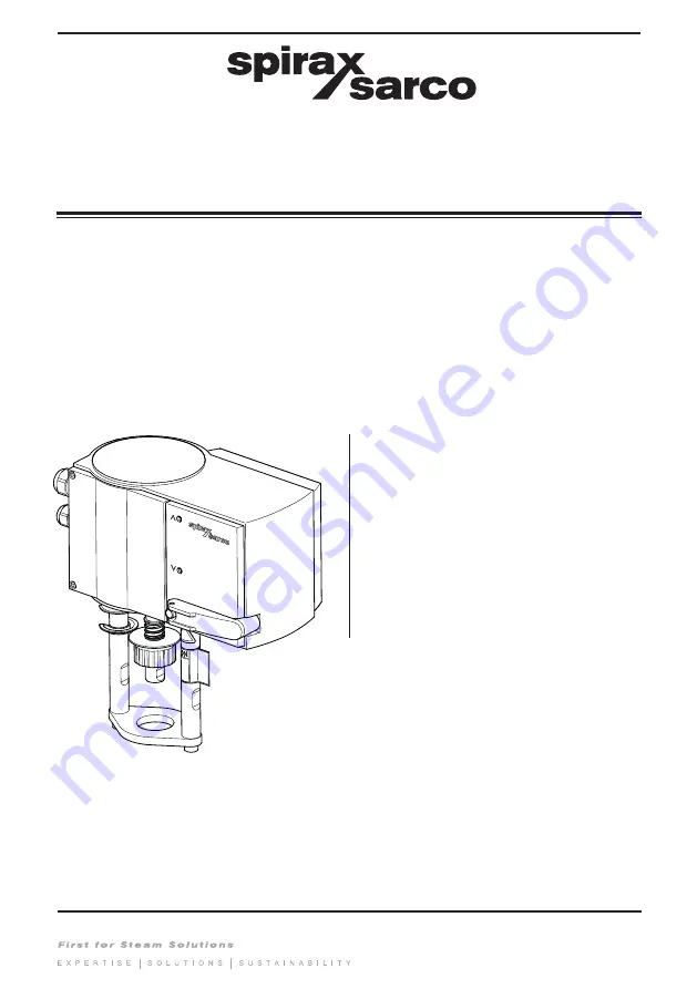
AEL3 

Electric Linear Actuators 

Installation and Maintenance Instructions

IM-P344-01

CTLS Issue 4

1. Safety information

2. General product information

3. Installation

4. Commissioning

5. Maintenance

© Copyright 2020 

Printed in GB

Summary of Contents for AEL3 Series

Page 1: ...uators 3583150 4 P100018817 B AEL3 Electric Linear Actuators Installation and Maintenance Instructions IM P344 01 CTLS Issue 4 1 Safety information 2 General product information 3 Installation 4 Commissioning 5 Maintenance Copyright 2020 Printed in GB ...

Page 2: ...correct installation Safety may be compromised if the installation of the product is not carried out as specified in this manual iii Isolate the actuator from the mains supply before opening the unit iv The actuator is designed as an installation category II product and is reliant on the building installation for overcurrent protection and primary isolation v Wiring should be carried out in accord...

Page 3: ...g excessive noise moving machinery Do not use the actuators in explosive atmosphere according the ATEX directive 2014 34 EU 1 7 The system Consider the effect on the complete system of the work proposed Will any proposed action e g closing isolation valves electrical isolation put any other part of the system or any personnel at risk Dangers might include isolation of vents or protective devices o...

Page 4: ...valves for regulating control cold warm or hot water steam or air and equivalent applications Typical use is for HVAC applications AEL3 actuators are available with 3 supply variants 24 Vac dc as standard 230 Vac or 100 Vac available with additional modules all being suitable for a VMD Valve Motor Drive input power signal or a 4 20 mA or 0 10 Vdc control signal The actuator has 3 speed options all...

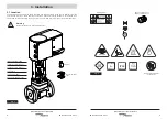
Page 5: ...land nut M20 x 1 5 Gland nut Adaptor Stroke indicator clips 3 1 Location The actuator should be mounted above the valve with sufficient space to remove the terminal cover and general ease of access When selecting the location make sure that the actuator is not exposed to an ambient temperature exceeding the range 10 C to 55 C Humidity 95 The actuator is rated at IP66 Warning Prevent access by non ...

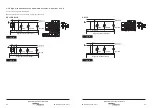
Page 6: ...IM P344 01 CTLS Issue 4 IM P344 01 CTLS Issue 4 10 11 AEL3 Electric Linear Actuators AEL3 Electric Linear Actuators 150 mm 150 mm Fig 3 Fig 4 ...

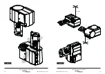
Page 7: ...o secure it Fig 5 Fig 6 click Actuator retaining nut Valve stem lock nut 2 x valve stem diameters 1 2 3 Note This symbol indicates an instruction sequence and appears throughout this document 4 Pull clamp ring up until it is heard to click Warning Risk of injury due to limbs being trapped Avoid contact with the danger areas click Fig 7 45 5 Make sure that the spindle is fully retracted into the ac...

Page 8: ...C 0 231 F 32 Fig 9 AEL3R AEL3X click OK AEL3E Manual Auto OR 9 Ensure handle is folded back against the actuator When mounting an actuator on a valve never drive the actuator electrically instead use the handle 8 For AEL3R and AEL3X use the handle to lower the actuator spindle until the clamp tightens over the adaptor For AEL3E fold the handle back to the home position in the actuator head and the...

Page 9: ... into the actuator and handle is up so that the spring is secured in place 4 Screw the coupling onto the stem and tighten the locking nut to secure it 5 Place the centering adaptor onto the valve bonnet thread 6 Place the mounting flange and actuator over the valve bonnet thread 7 Refit the actuator retaining nut and tighten 50 Nm for M30 8 Pull clamp ring up until it is heard to click 9 Using the...

Page 10: ...e attempting to wire the supply to the actuator 2 Slow blow fuses should be fitted in all phases but not in the protective earth conductor 3 The protective earth internal must be connected to the installation protective earth system The integrity of the installation protective earth system must not be compromised by the disconnection or removal of other equipment 4 For supply connections use 1 5 m...

Page 11: ...4 20 mA 0 10 V yo 0 10V 4 20 mA 0 10 V yo 0 10V 3 3 2 Signal connection for 24 V powered actuator 4 20 mA or 0 10 V Connect the wiring as per the diagram Note actuator action can be reversed via terminals 2a and 2b Fig 16 Signal to extend actuator Signal to retract actuator AEL3E AEL3R Fig 18 AEL3X Fig 17 Fig 19 Signal to extend actuator Signal to retract actuator ...

Page 12: ...plied to the regulating unit for the first time the automatic coupling with the valve and an initialisation take place During this process both LEDs on the drive flash in red 1 The spindle extends until it reaches the mechanical stop on the regulating unit 2 From this position the spindle retracts until it reaches the mechanical stop on the regulating unit 3 Initialisation is complete The regulati...

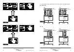
Page 13: ...s in manual mode AEL3X LED Description Both LEDs flash red Initialisation Top LED lights up red Top limit stop or OPEN position reached Bottom LED lights up red Bottom limit stop or CLOSED position reached Top LED flashes green Actuator is running moving to OPEN position Top LED lights up green Actuator is stopped last direction of travel OPEN Bottom LED flashes green Actuator is running moving to...

Page 14: ...the standard actuator model Fresh labels are provided that reflect the change made 1 Open the actuator cover 2 Slot in the appropriate power module in the space provided 3 Replace cover the original 24V wiring label on the inside of the actuator removable housing cover with fresh power module wiring label 4 Use provided power module marking label and affix it on the existing label located on the u...

Page 15: ...Actuators AEL3 Electric Linear Actuators X Y AEL3 X Y AEL3 Fig 33 X Y AEL3 Danger of electrocution Do not make a connection between terminal blocks X and Y Fig 33 100 110 V 230 V 0 10 V 4 20 mA 100 110 V 230 V 0 10 V 4 20 mA Fig 32 See next page for label detail Fig 34 Fig 35 ...

Page 16: ...2a 2b 21 N 2a 2b L N L N 3 7 1 Valve Motor Drive connection for actuators fitted with power module Fig 38 2pt 3pt 230 V 100 110 V L N L N Module 230 V 100 110 V Module 230 V 100 110 V 230 V 100 110 V AEL3E R AEL3E R AEL3E AEL3R AEL3X 2pt 3pt AEL3X AEL3X Fig 39 230 V 100 110 V 230 V 100 110 V Module 230 V 100 110 V Module 230 V 100 110 V L N L N Fig 36 Fig 37 ...

Page 17: ...v yo 0 10V Fig 43 L N 3 7 2 Signal connection for actuators fitted with a power module 4 20 mA or 0 10 V Note Actuator action can be reversed via terminals 2a and 2b Fig 40 230 V 100 110 V Module 230 V 100 110 V AEL3R AEL3E Signal to retract actuator Fig 41 230 V 100 110 V Module 230 V 100 110 V AEL3R AEL3E Signal to extend actuator AEL3E AEL3R Fig 42 230 V 100 110 V Module 230 V 100 110 V AEL3X A...

Page 18: ...or is disconnected from power supply 2 Remove all wiring from the terminals 3 Insert a flathead screwdriver in the slot as shown in the diagram 4 Depress the screwdriver and push it gently to the right to unlock the latch Be careful not to break it off 5 While applying gentle pressure on the latch pry the power module away from the actuator 3 9 Installing the auxiliary switches For use in normal e...

Page 19: ...ctric Linear Actuators 2 1 1 2 2 1 1 2 1 2 3 X S2 100 9 7 8 0 6 4 5 X S1 4 5 6 7 8 9 4 s 20 s 40 s 14 100 5 6 S1 100 7 8 9 S2 Nr 3 3 2 4 s 20 s 40 s 14 100 5 6 S1 100 7 8 9 S2 Nr 3 1 0 100 100 0 X S1 X S2 X S1 X S2 0 0 0 0 1 2 3 Fig 49 click Fig 50 Fig 51 Fig 52 Fig 53a Fig 53b Fig 54b Fig 54a ...

Page 20: ...S Issue 4 IM P344 01 CTLS Issue 4 38 39 AEL3 Electric Linear Actuators AEL3 Electric Linear Actuators 3 1 2 Fig 57 Note Overlay label also required for 24V variant as auxiliary switch is not UL approved Fig 55 Fig 56 ...

Page 21: ...o 240 C 1 Unscrew the actuator mounting plate screws for pillars 2 Screw the extension pillars into actuator pillars and tighten to 12 Nm 3 Screw the actuator mounting plate screws into pillars and tighten to 25 Nm 4 Mount the coupling extension into the actuator coupling until it snaps closed Fig 59 Fig 58 Note Overlay label also required for 24V variant as auxiliary switch is not UL approved Hig...

Page 22: ...d be adopted 4 1 Preliminary checks All actuators 1 Check that the actuator voltage corresponds to that required 2 Ensure the wiring corresponds to that outlined in Section 3 3 or 3 7 3 Ensure the assembly of the valve and actuator has been carried out according to the instructions in Section 3 2 4 Commissioning Always make sure that the electrical supply is switched off when carrying out maintena...

Page 23: ...IM P344 01 CTLS Issue 4 44 AEL3 Electric Linear Actuators Spirax Sarco Ltd Runnings Road Cheltenham GL51 9NQ United Kingdom www spiraxsarco com ...

Reviews: