background image

IM-P408-04 

EMM Issue 7

26

B850-W and B850-P Boiler House Energy Monitor

10.19 B850 energy monitor commissioning using 

PC software for quick start-up

The B850 energy monitor can be commissioned via the key pad on the front panel 

of the unit itself, or via separate PC software.

The B850 is supplied with a USB memory stick which contains the PC software, 

product manuals and associated files.

For quick start commissioning the PC software is used and illustrated in this manual.

1.

Plug the memory stick into a suitable empty USB connection on your PC / laptop.

2.

Using the windows operating sytem locate the PC Software on the memory stick 

(the file name is '850 vX.00.00_RC', where X is the version number). 

The icon looks like 

The software can be run from the memory stick or copied onto your PC / laptop.

3.

Double click on the icon to run the software. If presented with security warnings 

say yes to continue, or contact your IT administrator for guidance.

4.

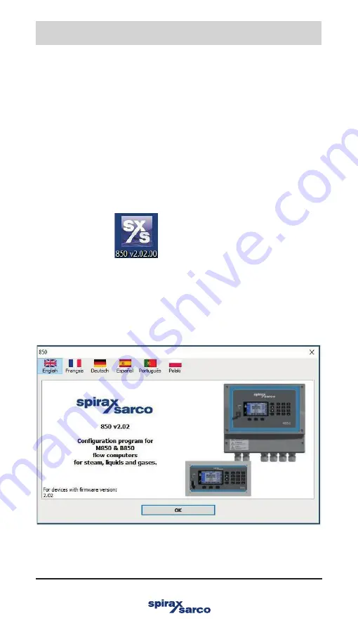
Select the language you wish the software to use (English, French, German, 

Spanish, Portugese or Polish). 

 Click' OK

10. Commissioning

Summary of Contents for B850-P

Page 1: ...ion 10 Commissioning 15 Appendix Copyright 2023 Printed in Poland 4080051 7 B850 W and B850 P Boiler House Energy Monitor Quickstart Guide IM P408 04 EMM Issue 7 Please note that this is the Quickstart Guide and that all relevant Sections for this product are contained in the main Installation and Maintenance Instructions IM P408 03 which is located on the electronic memory stick supplied B850 P 2...

Page 2: ...IM P408 04 EMM Issue 7 2 B850 W and B850 P Boiler House Energy Monitor ...

Page 3: ...ght to use the Work s solely within the scope of the legitimate operation of the product or device No other right is granted under this licence In particular and without prejudice to the generality of the foregoing the Work s may not be used sold licensed transferred copied or reproduced in whole or in part or in any manner or form other than as expressly granted here without the prior written con...

Page 4: ...to withstand the forces encountered during normal use Use of the product other than as a steam energy monitor or failure to install the product in accordance with these Instructions product modifications or repair could Cause damage to the product property Cause injury or fatality to personnel Invalidate the mark Isolate the mains supply before opening the product as hazardous voltages may be expo...

Page 5: ...d by any system to which they are fitted It is the responsibility of the installer to consider these stresses and take adequate precautions to minimise them 2 2 Access Ensure safe access and if necessary a safe working platform suitably guarded before attempting to work on the product 2 3 Lighting Ensure adequate lighting particularly where detailed or intricate work is required 2 4 Hazardous envi...

Page 6: ...ng a load by bodily force can cause injury particularly to the back You are advised to assess the risks taking into account the task the individual the load and the working environment and use the appropriate handling method depending on the circumstances of the work being done Arrange suitable lifting gear if required 2 10 Disposal The B850 contains a battery On disposal of the unit or component ...

Page 7: ...th ground terminal to enable the product to function correctly Not used to provide electrical safety Caution risk of electric shock Caution risk of danger refer to accompanying documentation Optically isolated current source or sink Caution Electrostatic Discharge ESD sensitive circuit Do not touch or handle without proper electrostatic discharge precautions ac alternating current dc direct curren...

Page 8: ...n Receipt of shipment Each carton should be inspected at the time of delivery for possible external damage Any visible damage should be recorded immediately on the carrier s copy of the delivery slip Each carton should be unpacked carefully and its contents checked for damage Content of B850 P 2 1 x Energy monitor B850 P 2 2 x Fixing clamps 1 x Printed Quick Start Guide 1 x USB Full installation a...

Page 9: ... of the product is required For cleaning use a dry cloth Do not use detergent or water 3 5 3 Serviceable parts There are no user serviceable parts battery is good for the life of the product 3 5 4 Returning faulty equipment Please return all items to your local Spirax Sarco representative Please ensure all items are suitably packed for transit preferably in the original cartons Please provide the ...

Page 10: ...SELV Binary outputs B850 W 2 and B850 W 2 UL Number of outputs 4 Type of outputs 3 pole COM NO NC electromechanical relay Contact rating resistive load 3 A at 85 250 Vac 30 Vdc Maximum switching voltage 250 Vac 125 Vdc Maximum switching power 750 VA 90 W Over voltage category CAT III Binary outputs B850 P 2 Number of outputs 4 Type of outputs 2 pole Solid State Relay Contact rating resistive load ...

Page 11: ...imum 8 W Enclosure B850 W 2 and B850 W 2 UL Protection class IP65 not UL evaluated Enclosure B850 P 2 Protection class front rear IP65 IP20 not UL evaluated Environmental conditions Ambient temperature 0 55 C 32 131 F Relative humidity 5 95 non condensing Altitude 2000 m 6 562 ft above sea level Pollution degree 3 Panel version when installed in an enclosure 3 Wall version Electrical safety EN 610...

Page 12: ...This product must be installed indoors only in one of the following ways Wall mounting Fit cable glands conduit with a minimum IP65 rating or install in a clean dry room to provide a pollution degree 3 environment in accordance with EN 60529 Specification for degrees of protection provided by enclosures IP code Any unused cable glands conduit entries must be sealed with an appropriate IP blind gro...

Page 13: ... shock and electrical interference The energy monitor should also be installed away from external magnetic fields such as those generated from electric motors and large transformers Other considerations Be sure to allow sufficient clearance for Installation of conduit wiring Viewing of the display Fig 13 Panel unit rear view Minimum 10 cm Minimum 10 cm Minimum 10 cm Minimum 10 cm Enclosure wall ...

Page 14: ...m No 10 screws 2 Remove the terminals enclosure cover to expose the bottom mounting holes Dimensions approximate in mm and inches B850 W non cULus version A B C D E F G H I J K L 257 00 mm 5 00 mm 217 00 mm 30 00 mm 10 60 mm 189 50 mm 10 00 mm 57 50 mm 26 00 mm 121 00 mm 242 00 mm 1 50 mm 10 12 0 20 8 54 1 18 0 42 7 46 0 40 2 26 1 02 4 76 9 53 0 06 3 x 5 mm 0 20 Mounting points F A C K J D I H E G...

Page 15: ...s X M O V U Q T S W Y N P R Dimensions approximate in mm and inches B850 W cULus version M N O P Q R S T U V W X Y 257 00 mm 5 00 mm 217 00 mm 21 00 mm 50 00 mm 39 00 mm 11 00 mm 61 00 mm 121 00 mm 242 00 mm 11 00 mm 189 50 mm 10 00 mm 10 12 0 20 8 54 0 83 1 97 1 54 0 43 2 40 4 76 9 53 0 43 7 46 0 39 ...

Page 16: ...Issue 7 16 B850 W and B850 P Boiler House Energy Monitor Bottom mounting eyelet access through the terminal compartment Fig 14 B850 W 2 Fig 15 B850 W 2 UL Bottom mounting eyelet access through the terminal compartment ...

Page 17: ...e terminals enclosure cover Note Before actioning any installation observe the Safety information in Section 2 Top mounting lug external Fig 16 3 Fix an M5 No 10 screw to the surface for the top mounting Leave the head of the screw proud of the surface just enough to allow the top mounting lug of the B850 to slide over Mounting screw left proud of surface to slot top mounting of B850 over ...

Page 18: ...ted version of the B850 energy monitor 2 Push the B850 through the aperture ensuring that the seal is fitted correctly 3 From the reverse side of the panel using the mounting points on the sides of the B850 assemble the fixing clamps to the body 4 Carefully wind in the clamps using the screwdriver slots to tighten the energy monitors to the panel Note Screw clamps removed for clarity Fig 17 Clamp ...

Page 19: ...ments for overcurrent protection 6 Overcurrent protection devices must be fitted to the relay circuit and appropriately rated for the given loads stated in the technical data 7 Relay contacts must be supplied at the same phase as the product s mains supply 8 The wall energy monitor B850 W is designed as an installation category product 9 Install wiring in accordance with IEC 60364 Low voltage elec...

Page 20: ... with the requirements for a disconnecting device specified in IEC 60947 1 or UL 60947 1 Specification for low voltage switchgear and controlgear General rules and IEC 60947 3 or UL 60947 3 Switches disconnectors switch disconnectors and fuse combination units 13 It is important that the cable screens are connected as shown in order to comply with the electromagnetic compatibility requirements 14 ...

Page 21: ...mendations see IM P408 03 Boiler House Energy Monitor Installation and Maintenance Instructions Screen connection An earth current loop is created if a wire or screen is connected between two earth points which are at different potential voltage If the instructions are followed correctly then the screen will only be connected to the earth at one end The earth terminal is a functional earth rather ...

Page 22: ...J 45 Wiring diagram from Section 15 Appendix IM P408 03 L L N E N O COM N C A B GND I I N E 1 2 3 13 14 15 19 20 21 1 A fuse Relay 1 of 4 100 240 Vac from supply Voltage free contacts 30 Vdc 0 1 A 240 Vac 3 A Modbus RTU slave 4 20 mA Output Ethernet LAN Relay 1 of 4 Relay 1 of 4 RS 485 RS 485 RS 485 Out 1 of 2 Out 1 of 2 ...

Page 23: ...tate TDS blowdown valve 0 Volt contact PRT EL2270 temperature probe for condensate return temperature PRT EL2270 temperature probe for feedwater temperature 0 4 20 mA MTL10 flowmeter for GAS m3 h or ft3 m 0 4 20 mA ELM flowmeter for make up water m3 h or gal m 0 4 20 mA ELM flowmeter for feedwater m3 h or gal m 0 4 20 mA EL2600 pressure sensor for steam pressure bar g or psi g 0 4 20 mA ILVA flowm...

Page 24: ... P boiler house energy monitor _ RJ 45 Wiring diagram from Section 15 Appendix IM P408 03 1 A B GND I I 2 3 16 17 13 14 15 19 5 4 Relay 1 of 4 24 Vdc 8 W maximum Solid state relay 24 V 0 1 A Modbus RTU slave 4 20 mA Output Ethernet LAN Relay 1 of 4 RS 485 RS 485 RS 485 Out 1 of 2 Out 1 of 2 ...

Page 25: ...t State TDS blowdown valve 0 Volt contact PRT EL2270 temperature probe for condensate return temperature PRT EL2270 temperature probe for feedwater temperature 0 4 20 mA MTL10 flowmeter for GAS m3 h or ft3 m 0 4 20 mA ELM flowmeter for make up water m3 h or gal m 0 4 20 mA ELM flowmeter for feedwater m3 h or gal m 0 4 20 mA EL2600 pressure sensor for steam pressure bar g or psi g 0 4 20 mA ILVA fl...

Page 26: ...e is used and illustrated in this manual 1 Plug the memory stick into a suitable empty USB connection on your PC laptop 2 Using the windows operating sytem locate the PC Software on the memory stick the file name is 850 vX 00 00_RC where X is the version number The icon looks like The software can be run from the memory stick or copied onto your PC laptop 3 Double click on the icon to run the soft...

Page 27: ... and select either imperial or metric units a pop up will appear allowing you to choose your fuel type This Quickstart IM has been written to be used in conjuction with the Gas Quickstart option choose Custom options if you requiring a different configuration Select units and then Gas Quickstart or fuel type custom To open an existing BEM configuration Click on File Open Settings file SET ...

Page 28: ...EMM Issue 7 28 B850 W and B850 P Boiler House Energy Monitor Use the windows operating system to locate and load the desired configuration file Select fuel type that the configuration was designed for and click OK ...

Page 29: ...onitor 10 21 BEM gas configuration quick start A partly configured BEM configuration will be presented Main applications The process values and inputs have been partly pre configured for the following applications A Steam output B Feedwater C Condensate return A B C ...

Page 30: ...cations H Click for process values I Set up for inputs J Set up for Relay Outputs K Configure Archives L Click to configure how data is displayed on the B850 s display M Setup the communications outputs N Media and characteristic manager O Admin and User configuration P Help and Comments appear throughout the software application Auxiliary applications Calculations and inputs have been partly pre ...

Page 31: ...k list and ticked off at each stages completion Save the configuration at each stage to minimise the risk of data loss This Quick Start instruction must be used with the B850 Boiler House Energy Monitor Installation and Maintenance Instruction IM P408 03 Tick when complete 10 23 Steam output see Section 10 23 Type V Size W Max F X Steam dryness Y Ref pres Z Ref temp 10 24 Feedwater see Section 10 ...

Page 32: ... mA IN3 Alarm IN3 Other IN4 4 mA IN4 20 mA IN4 Alarm IN4 Other IN5 4 mA m3 h or ft3 m IN5 20 mA m3 h or ft3 m IN5 Alarm IN5 Other IN7 Adjustment IN7 Alarm IN7 Other IN8 Adjustment IN8 Alarm IN8 Other IN10 Mode IN10 Unit IN10 Low Hz IN10 High Hz IN10 Other IN11 Mode IN11 Unit IN11 Low Hz IN11 High Hz IN11 Other Continued on page 33 10 26 Inputs continued from page 32 ...

Page 33: ...10 29 Condensate return process values see Section 10 29 Alarm Threshold Other 10 30 Fuel input see Section 10 30 Alarm Other 10 30 2 Fuel input calculation see Section 10 30 2 Calorific Value 10 31 Blowdown and TDS see Section 10 31 10 31 1 Bottom blowdown calculation see Section 10 31 1 Flow co efficient Kv Cv Enthalpy Density 10 31 2 TDS calculation see Section 10 31 2 Flow co efficient Kv Cv E...

Page 34: ...ler House Energy Monitor Tick when complete 10 32 Boiler efficiency see Section 10 32 Filter Alarm Threshold Other 10 33 Relay outputs see Section 10 33 RL1 RL2 RL3 RL4 10 35 4 20 mA output and other settings see Section 10 35 Continued from page 33 ...

Page 35: ...ter Max F and coefficients from the flowmeter calibration certificate this screen shot shows ILVA Set reference conditions typically not required Please refer to the flowmeter manual in this case ILVA for mechanical installation and Appendix 1 BEM Typical Wiring Diagrams ILVA flowmeters require V W X Y and Z coefficient values GILFLO flowmeters require A B C D and E coefficient values ...

Page 36: ...er Click on main applications then B the feedwater application will be displayed Set reference conditions typically not required Please refer to the flowmeter manual in this case ELM for mechanical installation and set up of its 4 20 mA output and Appendix 1 BEM Typical Wiring Diagrams ...

Page 37: ...in applications then C the condensate return application will be displayed Set reference conditions Please refer to the flowmeter manual in this case ELM for mechanical installation and set up of its 4 20 mA output and pages 13 to 16 for the Wiring Diagrams The nominal pressure must be determined and entered ...

Page 38: ...m Output is used to give a pressure figure for the feedwater input B T W input 7 for the feedwater temperature set Pt100 parameters Condensate Return inputs C SW input 4 for the make up water ELM flowmeter range 4 20 mA input C T W input 8 for the condensate return temperature set Pt100 parameters GAS Flow inputs X Qv input 5 for GAS MTL10 flowmeter range 4 20 mA input Blowdown Y Vb input 11 for B...

Page 39: ...P408 04 EMM Issue 7 39 B850 W and B850 P Boiler House Energy Monitor Range the 4 20 mA inputs for the flowmeters on inputs 1 3 4 and 5 and pressure sensor on input 1 Set Pt100 parameters for input 7 and 8 ...

Page 40: ...or Set ranges for BBD and TDS controller inputs on input 10 and 11 Valve Circuit Value Open closed 1 Closed open 0 PULS type inputs IN10 IN11 and IN12 may be set as 0 volt contacts for automated TDS Blowdown and Bottom Blowdown systems Ensure voltage does not exceed 40 V ...

Page 41: ...k on the process values Thresholds T totalisers t alarms A and graph settings G can be set up for the Steam Output Process for full details see B850 Boiler House Energy Monitor Installation and Maintenance Instructions IM P408 03 The Quickstart Configuration is pre configured with suitable settings It is recommended that at least 1 totaliser for Steam Output Process is configured G T A t ...

Page 42: ... totalisers t alarms A and graph settings G can be set up for the Feedwater Process for full details see B850 Boiler House Energy Monitor Installation and Maintenance Instructions IM P408 03 The Quickstart Configuration is pre configured with suitable settings The Quickstart Configuration is pre configured with suitable settings It is recommended that at least 1 totaliser for the Feedwater Process...

Page 43: ...ayed Click on the process values Thresholds T totalisers t alarms A and graph settings G can be set up for the Condensate Return for full details see B850 Boiler House Energy Monitor Installation and Maintenance Instructions IM P408 03 The Quickstart Configuration is pre configured with suitable settings It is recommended that at least 1 totaliser for Condensate Return is configured G T A t ...

Page 44: ...olds T totalisers t alarms A and graph settings G can be set up for the Fuel Input Flowrate for full details see B850 Boiler House Energy Monitor Installation and Maintenance Instructions IM P408 03 The Quickstart Configuration is pre configured with suitable settings Please refer to the flowmeter manual in this case MTL10 for mechanical installation and set up of its 4 20 mA output and pages 15 t...

Page 45: ...sers t alarms A and graph settings G can be set up for the Fuel Input Calculation for full details see B850 Boiler House Energy Monitor Installation and Maintenance Instructions IM P408 03 The Quickstart Configuration is pre configured with suitable settings It is recommended that at least 1 totaliser for Fuel Input Calculation is configured G T A t ...

Page 46: ... 3600 Where 3600 converts from h to sec Calculation for Imperial MBtu h X Qv 1 60 1000 A calorific value CV for the fuel must be entered into the calculation Click on Edit the 1 in the above calculation and add the calorific value for your fuel type The calorific value CV must be entered in units of Btu ft3 Qv Flowrate measured on Input 5 in ft m Depending on the output of the fuel flowmeter a uni...

Page 47: ...input calculation will then be displayed input values required Click on the process values Thresholds T totalisers t alarms A and graph settings G can be set up for the Bottom Blowdown Calculation for full details see B850 Boiler House Energy Monitor Installation and Maintenance Instructions IM P408 03 The Quickstart Configuration is pre configured with suitable settings G T A t ...

Page 48: ...ity kg m Derive the value for your boiler from the look up tables in Section 10 31 3 Other measured units Pressure bar and Relative Density kg m It is assumed that there will be a backpressure of 10 so a factor of 0 9 can be seen in the calculation If backpressure is different adjust formula accordingly Y Vb 1 1 1 s qr t A p D 0 9 10 0 0 1 3600 Density Kv When you enter this screen a pop up will b...

Page 49: ...156 Enthalpy Btu lb Derive the value for your boiler from the look up tables in Section 10 31 3 Density lb ft Derive the value for your boiler from the look up tables in Section 10 31 3 Other measured units Pressure psi and Relative Density lb ft It is assumed that there will be a backpressure of 10 so a factor of 0 9 can be seen in the calculation If backpressure is different adjust formula accor...

Page 50: ...will then be displayed input values required Click on the process values Thresholds T totalisers t alarms A and graph settings G can be set up for the Bottom Blowdown Calculation for full details see B850 Boiler House Energy Monitor Installation and Maintenance Instructions IM P408 03 The Quickstart Configuration is pre configured with suitable settings G T A t ...

Page 51: ...ler pressures Density Enthalpy bar g kg m3 kJ kg 5 915 3 640 0 10 887 2 762 3 15 886 8 844 3 20 849 9 908 2 Typical boiler pressures Density Enthalpy psi g lb ft3 Btu lb 100 56 39 298 49 150 55 29 330 58 200 54 39 355 45 250 53 61 376 18 300 52 92 394 02 10 31 3 Tables for TDS and BBD ...

Page 52: ...Derive the value for your boiler from the look up tables in Section 10 31 3 Other measured units Pressure bar and Relative Density kg m It is assumed that there will be a backpressure of 10 so a factor of 0 9 can be seen in the calculation If backpressure is different adjust formula accordingly Density Enthalpy Kv Y Vt 1 1 1 s qr t A p D 0 9 10 0 0 1 3600 When you enter this screen a pop up will b...

Page 53: ...156 Enthalpy Btu lb Derive the value for your boiler from the look up tables in Section 10 31 3 Density lb ft Derive the value for your boiler from the look up tables in Section 10 31 3 Other measured units Pressure psi and Relative Density lb ft It is assumed that there will be a backpressure of 10 so a factor of 0 9 can be seen in the calculation If backpressure is different adjust formula accor...

Page 54: ...ues then Z the boiler efficiency calculation will bedisplayed Click on the process values Thresholds T alarms A and graph settings G can be set up for the Boiler Efficiency for full details see B850 Boiler H ouse Ener gy M o nito r Installation and Maintenance Instructions IM P408 03 Check Select filter and set to 30 mins ...

Page 55: ...7 to Section 10 32 you can set the relay activity they can also be ascociated with Alarms Click on applications to select process values Click to highlight process value desired and then click in desired row of display To remove a process value from the display right click on the display row and click remove Applications Display rows Process values 10 34 Display screen settings Click on screen set...

Page 56: ... own protocol Modbus RTU protocol and BACnet MSTP Ethernet port available is web server Modbus TCP protocol and BACnet IP In addition the RS 485 port can be used to connect the GSM module it enables transfer of information about failures alarms and measurement values in the form of SMS text messages For further details on the Sections listed above and for functions Media and Characteristic Manager...

Page 57: ...e to either the PC laptop or memory stick if you require to configure the system further Save the configuration onto the memory stick if you wish to load it onto the B850 C Users user name Desktop My Config It may be useful to limit your file name to 8 characters in length as the B850 will truncate longer file names when displaying them on its screen ...

Page 58: ...move the dust plug from the USB terminal on the front of the B850 and plug in the memory stick MAIN MENU Load or Save settings Load Highlight your file and click LOAD button you configuration will now be loaded You will be asked to confirm the action click YES If you are not already logged in you will be asked to enter a password see IM P408 03 Installation and Maintenance Instructions for ADMIN p...

Page 59: ...IM P408 04 EMM Issue 7 59 B850 W and B850 P Boiler House Energy Monitor Click OK and the unit will restart with the configuration loaded ...

Page 60: ...ressure measurement rD Steam density hD Steam enthalpy DpD Pressure difference at orifice in differential pressure device only if differential pressure device was chosen Applications B Section 10 24 and 10 28 PW Feedwater heat flowrate qm W Feedwater mass flowrate qv W Feedwater volume flowrate TW Feedwater temperature rW Feedwater density hW Feedwater enthalpy Applications C Section 10 25 and Sec...

Page 61: ... X Section 10 30 Qv Gas mass flowrate Pg Computed value Application Y Section 10 31 Vb Measurement bottom blowdown valve input Pb Computed value bottom blowdown Vt Measurement TDS valve input Pt Computed value TDS blowdown Application Z Section 10 32 E Computed value boiler efficiency ...

Page 62: ...Panel mounted B850 P boiler house energy monitor 48 24 V I U I I F I U FIN 43 44 45 61 62 64 65 63 66 73 74 75 In 6 In 9 In 9 In 6 In 9 In 12 In 6 In 9 In 12 47 24 V I U I I F I U FIN 44 45 46 58 61 59 60 62 69 70 71 In 6 In 9 In 9 In 6 In 9 In 12 In 6 In 9 In 12 0 4 20 mA input RTD input PULSE input 0 4 20 mA input RTD input PULSE input ...

Page 63: ...of the result for all related channels e g for measurement input and the calculation channel in which the result is used No signal from the sensor assigned to the particular input is treated as a failure and marked on the display with the F failure symbol Detection of a failure may trigger displaying the appropriate message and then require confirmation by the user even if the cause of the failure...

Page 64: ...IM P408 04 EMM Issue 7 64 B850 W and B850 P Boiler House Energy Monitor ...

Reviews: