background image

IM-P481-04 

CTLS Issue 4

41

The following page provides access to historical alarm list. This allows the user to view previously triggered alarms.

Alarms indication icon

Manual alarm 

indication icon

Caution - high-limit 

setting

-

If fitted, the high-limit controller should be set at a suitable level to protect plant, process and personnel.

-

Care should be taken to ensure sufficient difference between the process set point and the high-limit set 

point, to avoid any unwanted high limit tripping.

-

Check temperature rises to set value and controls satisfactorily.

-

If necessary adjust PID settings. We would strongly recommend that only a suitably trained controls 

engineer adjust these parameters.

-

Check operation of steam traps/condensate pump.

Fig. 51

Summary of Contents for EasiHeat

Page 1: ... information 3 Installation 4 Commissioning 5 Fault finding 6 Maintenance Copyright 2018 Printed in GB 4819050 4 Spirax EasiHeatTM DHW Potable and Process Water Heating Compact Heat Transfer Solution Installation and Maintenance Instructions IM P481 04 CTLS Issue 4 ...

Page 2: ... the scope of the legitimate operation of the product or device No other right is granted under this licence In particular and without prejudice to the generality of the foregoing the Work s may not be used sold licensed transferred copied or reproduced in whole or in part or in any manner or form other than as expressly granted here without the prior written consent of Spirax Sarco Limited ...

Page 3: ...ient space should be provided around the systems location to allow access for maintenance Warnings General 1 This product is designed and constructed to withstand the forces encountered during normal use 2 Use of the product for any purpose other than its intended use could cause damage to the product and may cause injury or fatality to personnel 3 Before any installation or maintenance procedure ...

Page 4: ...ow iv Spirax Sarco products are not intended to withstand external stresses that may be induced by any system to which they are fitted It is the responsibility of the installer to consider these stresses and take adequate precautions to minimise them v Remove protection covers from all connections and protective film from all name plates where appropriate before installation on steam or other high...

Page 5: ...g to protect against the hazards of for example chemicals high low temperature radiation noise falling objects and dangers to eyes and face 1 11 Permits to work All work must be carried out or be supervised by a suitably competent person Installation and operating personnel should be trained in the correct use of the product according to the Installation and Maintenance Instructions Where a formal...

Page 6: ...ected separately The base unit of the Spirax Sarco EasiHeat DHW provides the core of the system while options see Sections 2 2 provide additional features such as high limit package stop valve package and energy monitoring The Spirax Sarco EasiHeatTM DHW unit consists of the following core items refer to Figure 1 A Plate heat exchanger B Pneumatic or electrically actuated control valve and positio...

Page 7: ...tion EL Electric EL PN Pneumatic Condensate removal ST Steam trap ST PT Pump trap PTHC Pump trap high capacity Mechanical options High limit HL Integrated high limit HL IHL Independent high limit High limit actuation EL only B Battery back p C C Super capacitor Isolation V1 Ball valve V2 V2 BSA V3 DBB3 Gasket material G1 EPDMPC G1 G2 Heatseal Extras W Wheels W S EN 12828 safety option S Panel opti...

Page 8: ...afety valve to protect any lower pressured equipment on either the hot or cold side of the plate heat exchanger is strongly recommended Spirax Sarco supplies a range of traps strainers separators safety valves and pressure reducing equipment 3 2 Air supply If a pneumatic control system is installed connect a compressed air supply 4 5 to 8 bar g 65 to 116 psi g to the pressure regulator mounted on ...

Page 9: ...ature sensors 3 wire 3 5 Electrical connections The following are available for customer connection to the Spirax Sarco EasiHeat system if required Volt free contacts Terminal designation Description Type X14 Enabled running signal 1 x N O contact 1 x N C contact X15 High Limit alarm 1 x N O contact 1 x N C contact X16 Band Alarm 1 x N O contact 1 x N C contact Fig 3 VOLT FREE ENABLE SIGNAL K1 7 2...

Page 10: ...ation Description Type X7 Remote set point 4 20 mA input X17 Remote enable 24 Vdc signal X9 Retransmission value 4 20 mA output Fig 4 CHANNEL 13 4 20mA REMOTE PID LOOP SETPOINT X7 2 1 3 2 1 3 2 1 3 001 001 X17 X9 24 3 162 REMOTE SYSTEM ENABLE CHANNEL 0 RETRANSMISSION OF PV OR VALVE POSITION ...

Page 11: ...ature OUT X3 Steam temperature X4 Condensate temperature X5 High limit temperature Group X6 to X10A X6 Linear actuator feedback X7 Remote PID loop set point requires 4 20mA input X8 Steam flow X9 Retransmission value X10A Linear actuator control position Group X10B to X11 X10B Linear actuator closed signal X10C Linear actuator supply voltage Electric actuator only X11 Bypass pump X12 Bypass valve ...

Page 12: ... diagram Section 3 3 Figure 2 Dry commissioning valve stroke check An initial valve stroke check should be carried out to ensure free movement of the valve stem 1 For the electric actuated control valve use the manual override on top of the actuator to raise and lower the actuator spindle between the two travel indicators located on the side of the pillar Figure 6 2 For the pneumatic actuated cont...

Page 13: ...t the number then press OK to confirm your selection repeat until all numbers are entered 4 2 TVA quick commissioning The TVA flowmeter is factory set to display data in metric units changeable to imperial if required by following the flow chart Figure 10 or the individual product Installation and Maintenance Instructions IMI All commissioning of the TVA is through the arrow buttons located on the...

Page 14: ...its In Kg or lb kWh or kBTU Normal run mode display sequence Power on sequence turn on all segments then show the software version no Error Messages These alternate with the normal run mode display They will be prioritised and will be latched when they occur Pressing the OK button will cancel the displayed alarm and allow the next one to be viewed A continuous alarm will re occur on the display 2 ...

Page 15: ...iguration sub menus xxxx BASIC dAtA MEtER OUtPUtS 4 20 mA SORCE FLOW POWER SEt 4 mA xxxxx CHECK 4 mA OP 4mA CHECK 20 mA OP 20 mA Connect a DVM and use the up and down keys to set 4 or 20 mA in kg h or lb h kW or Btu h SEt 20 mA xxxxx ...

Page 16: ...pletes the basic requirement for scaling of the TVA flowmeter suitable for integration with the HMI The next menu Sorce will need FLOW to be selected Obtain the correct flow data from the Spirax Sarco EasiHeatTM specification sheet supplied for accuracy thereafter navigate down the menu and input Minimum flow 4 mA Maximum flow 20 mA OUtPUtS 4 20 mA PULSE OUtPUtS 4 20 mA SORCE FLOW POWER SEt 4 mA x...

Page 17: ...wer up Fig 13 When ready the above screen will appear touch the screen If the unit has not been configured for previous use following page will appear To be able to move to next page the unlock code is essential after entering the proper code found on the software authentification document the lock and the continue button will appear which will transfer you to the time date setting page Fig 14 ...

Page 18: ... default one of the following four pages will appear pre configured for designated region By choosing the relevant flag for your Country the common default engineering units and language will automatically be selected for that region These values can be changed after the initial commissioning set up procedure has been completed see Section 4 5 3 Fig 15 Fig 17 Fig 19 ...

Page 19: ...arco EasiHeatTM unit that is available is dependent on the flag selection The next screen Figure 20 requires confirmation of the system to be configured Fig 20 The selection shall be confirmed by the icon becoming highlighted with a red surround and a continue button shall be revealed Press the continue button to advance to the system configuration menu ...

Page 20: ...he icon Fig 22 System configuration should match the mechanical configuration of the Spirax Sarco EasiHeatTM and control system of the plant proper configuration will show or hide options available after configuration Some of the screens may contain additional options which with specified configuration may be hidden all the options are described in this document ...

Page 21: ... 24 turn actuator selection Local Remote Communications Fig 27 Enable control selection No position feedback Position feedback Fig 26 Linear actuator control signals Electrical Pneumatic Fig 25 Linear actuator selection Single safety interlock Double safety interlock DP27E Local Remote Communications Fig 28 PID set point selection Not installed Installed Fig 29 TVA flowmeter selection Disabled Ena...

Page 22: ...Start Page Figure 13 page 16 Blue hand TVA installed and remote set point selected On TVA flowmeter selection a data entry point shall be displayed in order for effective scaling of the flowmeter full engineering range for the 4 20 mA signal input to the Spirax Sarco EasiHeatTM system The full range values entered at this point should match exactly those that are programmed in the TVA flowmeter pa...

Page 23: ...co EasiHeatTM system Press the continue button to navigate to the energy set up page Accurately enter specific energy data to ensure valid energy data can be calculated Boiler fuel properties Selected via the drop down menu Boiler feedwater temperature Boiler efficiency Cost per unit of fuel Override energy set points with BACnet set points Fig 33 ...

Page 24: ...ting the custom fuel type Custom fuel parameters to be set Fuel calorific value Fuel specific gravity Fuel emission factor Fuel conversion heat factor Energy setting will not affect control process to obtain correct values of the calculated energy the accurate data settings are essential ...

Page 25: ...ured From this home screen the overall status and control of the Spirax Sarco EasiHeatTM systems operation can be performed depending on the security level access Images shown below are dialogue pages that are only available for engineers access which allow control over the valves it is possible to enter those dialogs by pressing the screen surface at one of the unit devices valves This will allow...

Page 26: ...Manual mode The light indicator shows what mode is selected V1 dialog page contains two value fields the top one show the actual valve position and the bottom one can be used to move the valve to requested position in manual mode Open Start Close Stop ...

Page 27: ... with local temperature set point PID set point This pop up menu depending on the communications allows users to either set the local temperature set point or view the remote or BACnet temperature set point and enter the Spirax Sarco EasiHeatTM system PID associated ramp up and ramp down time bases If the configuration were set to BACnet it is possible to override the configuration and change it t...

Page 28: ...co EasiHeatTM or view the remote or communications enable status If the configuration were set to BACnet it is possible to override the configuration and change it to local enable configuration Spirax Sarco EasiHeatTM OFF mode Spirax Sarco EasiHeatTM ON mode Remote or communications enable Communications enable override with local Spirax Sarco EasiHeatTM Fig 38 ...

Page 29: ...IM P481 04 CTLS Issue 4 29 Zoom The zoom pop up provides a more detailed view of the key process parameters Fig 39 ...

Page 30: ...system The anti legionella control and set point page is accessible from a button located on the main screen There are two modes of operation for the anti legionella cycle that are selectable from the HMI pop up screen these are Manual Automatic timed Warning The temperature set point during this cycle will exceed normal operating temperatures and could cause scalding if water is used during the c...

Page 31: ...nella boost temperature that the EasiHeatTM must achieve during a cycle Note that the temperature setting must not exceed that of the Independent High Limit IHL if fitted This is the time set point for the manual cycle boost in which the cycle will be performed During this time the process temperature request will be overridden by the temperature entered in the anti legionella boost cycle setting ...

Page 32: ...4 CTLS Issue 4 32 Finally the unit must be manually enabled from the enable request pushbutton located on the HMI the user can stop the anti legionella boost cycle at any time by pressing the same button Fig 43 ...

Page 33: ...can be used to shut the cycle down early if required by pressing the Enable Disable button as per the manual operation Note When enabled in either mode of control the process set point temperature used to control the PID loop and proportional valve is overridden by the anti legionella temperature set point The anti legionella set point is still governed by the same ramp up and ramp down rates as t...

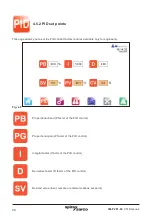
Page 34: ...n P factor of the PID control Integral factor I factor of the PID control Derivative factor D factor of the PID control Desired value local remote or communications set point 4 5 2 PID set points This page allows you to set the PID control factors entries available only for engineers Fig 45 ...

Page 35: ...e Allows to configure the PID set points with view of the actual signals The following screen is accessible from above PID Loop Set Points page available only for engineers We are able to switch between proportional band and proportional gain Trend shows us PID loop real time responses The SV PV and CV values at PID Real Time Trend are scaled to percent ...

Page 36: ...mperature units selection Flowmeter units selection Energy monitoring only Energy units selection Energy monitoring only 4 5 3 Settings menu The settings displayed with blue surround are default settings after the country flag has been selected changes can be made if required Fig 47 ...

Page 37: ...ossibility of changing the language from the pre configured options by using the following selection menu without affecting the engineering units In addition engineers are able to set or change the actual time and date for PLC and HMI Fig 48 Fig 49 ...

Page 38: ... the alarm bell in the top left hand corner of the screen There are also navigations to further alarm set point pages as well as the historical alarm list located on the right of the display Press each of them to view or alter High limit alarm set point PLC controlled only High limit temperature set point High limit temperature mask time Fig 50 ...

Page 39: ...IM P481 04 CTLS Issue 4 39 2 C Band alarm Band alarm temperature set point Band alarm delay time set point Band alarm reset time set point Deviation alarm Deviation alarm set point ...

Page 40: ... min Rate of change alarm DHW only Temperature rate of change alarm set point Process set point reduction set point Alarm reset time set point Reset high limit alarm latch PLC controlled high limit only Historical alarm page 2 10 0 C C min ...

Page 41: ...e set at a suitable level to protect plant process and personnel Care should be taken to ensure sufficient difference between the process set point and the high limit set point to avoid any unwanted high limit tripping Check temperature rises to set value and controls satisfactorily If necessary adjust PID settings We would strongly recommend that only a suitably trained controls engineer adjust t...

Page 42: ...TLS Issue 4 42 4 5 5 Trend menu This menu provides historical trend monitoring of the process values useful for analysing the historical reactions of the Spirax Sarco EasiHeatTM system to process conditions Fig 52 ...

Page 43: ... button energy monitoring only Flow trend page button energy monitoring only Temperature trend page button PID process trend page button Scroll trend left Zoom in trend Zoom out tend Move trend to actual position Refresh trend Scroll trend right ...

Page 44: ...at is correct FAT32 only allowed This LED is switched on only during the trend dump do not remove the memory stick before it is switched off or data may be lost Total unit runtime 4 5 6 Service menu The following page provides service information and allows engineering level users to navigate to pages containing process information Fig 53 ...

Page 45: ...mber of hours Next service due at number of hours Process enable event count High limit event count Local Spirax Sarco engineer contact details dialog page Hardware monitoring pages input output overview Restore commissioned set points access level 2 ...

Page 46: ...46 4 5 7 Hardware monitoring The following pages provide only an overview of the input and outputs it is not possible to set any set points Fig 54 Figures 55 56 57 and 58 display the analogue input and output values Fig 55 CPU ...

Page 47: ...IM P481 04 CTLS Issue 4 47 Fig 56 Digital input Fig 57 Analogue inputs Fig 58 Analogue retransmission outputs ...

Page 48: ...rgy monitoring pages provide the user access to view the total value of the power and carbon use total of CO2 emission and calculated total cost of energy that has been used By pressing the green field underneath the Total Between Two Dates allows two dates to be set for the total to be calculated between Fig 60 ...

Page 49: ... point This will go to the energy page Energy monitoring set points page Fig 61 To finalise the mechanical commissioning of the system Open all condensate drain valves Slowly open the steam inlet valve Monitor the process temperature to ensure that it is within the acceptable limits The Spirax Sarco EasiHeatTM unit is now ready for service ...

Page 50: ...ield wiring fault Check termination of 3 wire PT100 terminats X1 X5 and PT100 head Faulty PT100 Check compensated resistance Bypass pump does not operate Field wiring fault Check wiring of pump to terminals X11 Internal fuse blown Check mains fuse F4 Bypass valve does not operate Field wiring fault Check wiring of bypass valve to terminals X12 Check setting of deviation alarm on HMI Ensure not to ...

Page 51: ... Loss of loop power Check control fuse CF3 TVA input is not showing correctly Scaling value incorrect Ensure that the minimum and maximum engineering units from the TVA commissoining match those on the HMI this data is found on the Spirax Sarco engineers 4 20 mA page Polarity of 4 20 mA incorrect Reverse polarity and wire as per electrical drawings ...

Page 52: ...a frequent basis Intervals between tests should not exceed a six month period We do not recommend the installation of a self acting high limit control to the Spirax EasiheatTM system 6 3 Scale formulation Within open systems where there is continual make up water there is a risk of scale formation The extent of the scale will depend largely upon the water quality which varies greatly from area to ...

Reviews: