10
Section 5
Recirculation Systems
A problem many hot water systems encounter is the
delayed supply of hot water to fixtures that are a substantial
distance from the heater. During idle periods, heat loss in
the piping system will result in cool water at the tap until hot
water produced from the heater is able to reach that point.
Delays in providing hot water at the tap can result in user
dissatisfaction.
The compactness of the RediHeat permits installation close
to the point of use in many cases. However, in systems with
long pipe runs, conditions may exist where the supply of hot
water at the faucet will be delayed.
To provide instantaneous hot water on demand in systems
with long pipe runs, various methods can be utilized. The
appropriate system will be influenced by site conditions,
plan requirements, and user preference.
The following describes several systems and their interaction
with the RediHeat instantaneous heater:
A. Heat Tape Systems
Many building systems avoid the costly pipe runs of
conventional loop or return systems. Instead, electrical
resistance heat is applied to the pipe in tape form to replace
heat lost from the system. This method can be very effective
and the RediHeat will function perfectly with this type of
system. Heat tape installed up to the hot water outlet of the
control valve will assure maximum performance.
B. Bleed System
This system consists of a single line distribution pipe with a
thermostatically operated bleed valve. A temperature switch
is set to open the bleed valve if the line temperature falls
below the system set point. Upon opening, water in the line
is dumped to drain until heated water from the RediHeat
fills the line and signals the valve to close. This cycle will
continue to hold the water temperature within set limits.
This system eliminates the costs of return piping and
circulation pumps, however the cost of water consumption
may prove too high for many installations.
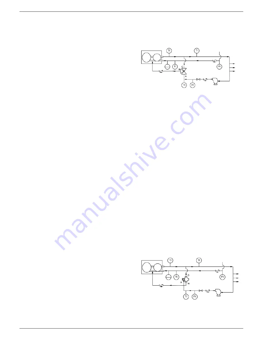
C. Forced Recirculation Loop - Diverting Valve with
Fixed Thermostat:
Most systems incorporate a circulating pump to maintain
constant flow in a forced recirculation loop. The RediHeat
is used to maintain loop temperatures as well as supply
demand requirements. The system includes a self contained
3-way thermostatic type diverting valve to direct the
recirculated water flow as required. The diverting valves
normally are provided with fixed thermostatic elements.
Models with adjustable elements are also available (see
section D).
Water flow in the system is governed by the temperature
of the recirculating loop. When the loop is at the desired
temperature, the flow of recirculated water by-passes the
RediHeat. As the temperature in the loop decreases due
to heat loss through the piping, the thermostatic element
responds and causes a portion of the water to be diverted
through the RediHeat. Typical recirculated flow rate is
10% of the RediHeat capacity, however more accurate
calculation methods should be used in complex systems.
Installation of the diverting valve is as shown. If you have
any questions regarding installation, contact Spirax Sarco.
Incorrect installation can lead to serious overheating of the
water, resulting in dangerous temperatures.
D. Forced Recirculation Loop (Diverting valve with
adjustable thermostat):
In addition to the fixed thermostatic element diverting valve,
Spirax Sarco offers as an option an adjustable diverting
valve. The adjustable diverting valve can be used to provide
additional flexibility in the temperature of the hot water when
the system is in the recirculation mode. The valve supplied is
a Lawler Thermostatic Water Controller or equal. As Spirax
Sarco uses the valve in a non-typical manner, do not follow
the standard installation instructions supplied by the valve
manufacturer. The following should be used as a guide for
installation of this system.
Connect the Lawler port labeled “outlet” to the recirculating
loop return line. This is the flow into the valve from the
circulating pump, indicated as “A” below.
Connect the port labeled “H” (hot water inlet) to the cold
water supply line feeding the RediHeat. This port will open
when the recirculation loop water has cooled, and sends a
portion back to the RediHeat for reheating.
Connect the port labeled “C” (cold water inlet) to the hot
water supply line feeding the recirculation loop. This port
is open when the recirculation loop water is at the desired
set point and allows the recirculating water to by-pass the
RediHeat.
Installation of the diverting valve is as shown. If you have
any questions regarding installation, contact Spirax Sarco.
Incorrect installation can lead to serious overheating of the
water, resulting in dangerous temperatures.
Diverting Valve
(Fixed Thermostat)
*
RediHeat
Cold Water
Supply
Hot
Water To
Users
Diverting Valve
(Fixed Thermostat)
*
RediHeat
Cold Water
Supply
Hot
Water To
Users
* A Thermal expansion tank may be required when the cold
water inlets include check valves.
* A Thermal expansion tank may be required when the cold
water inlets include check valves.


