8
install lower diaphragm case (5) securing it with cap
screws (14) tightening in a sequential manner (note
location of notch in relation to valve body).
7. Install adjustor key cylinder (25) on the pin located on
the valve shaft. Replace O-ring on temperature control
rod (18) and insert so adjustor key is centered in slot
and notch on control rod fits with groove pin in adjusting
sleeve (27). Install circlip (23) and locking ring (21).
8. Install, in order, the control valve spring (10), spring
guide washer (16), diaphragm plate (11), diaphragm
(13), O-ring (9), shouldered washer (8), and jam nuts (7),
on main valve stem. Position diaphragm over holes and
notch on lower case prior to tightening the jam nuts.
9. Install upper cover (6) and be sure notches in lower
cover, diaphragm and upper cover line up. Install bolts
and tighten sequentially.
10. Install valve on frame.
11. Install sensing tube (46) and Victaulic fittings. Check all
fittings for tightness.
12.
Refer to start-up procedures for temperature
adjustment.
3.3 Heat Exchanger Inspection Disassembly
The heat exchanger coil is readily accessible for inspection
and cleaning without disturbing the steam or water piping.
Procedure
1. Remove plug to drain the casing.
2. Remove all base plate nuts (93 or 94).
3. Lift off the casing (80 or 81), being careful not to damage
the gasket (84 or 85).
4. If a leak in the tubing is suspected, water pressure can
be turned on. Any leaks should be easily seen with the
unit still in place.
To Clean the Coil
Depending on local water conditions, scale deposits from
hard water can form inside the heat exchanger coil. The
coil can be cleaned in place using an acid pump cleaning
system employing the following procedure:
1. Remove the two cast bronze elbow manifolds from
the heat exchanger by disassembling the four Victaulic
couplings.
2. Attach the 3/8” nipple supplied with the acid cleaning
system adaptor kit to one of the adaptors.
3. Insert this adaptor into the heater connection closest to
the center of the exchanger.
Note:
the 3/8” nipple must extend up into the exchanger.
4. Secure the adaptor with one of the Victaulic couplings
removed in Step 1.
5. Connect the other adaptor to the remaining exchanger
connection with a Victaulic coupling.
6. Connect the acid hoses, pump and reservoir.
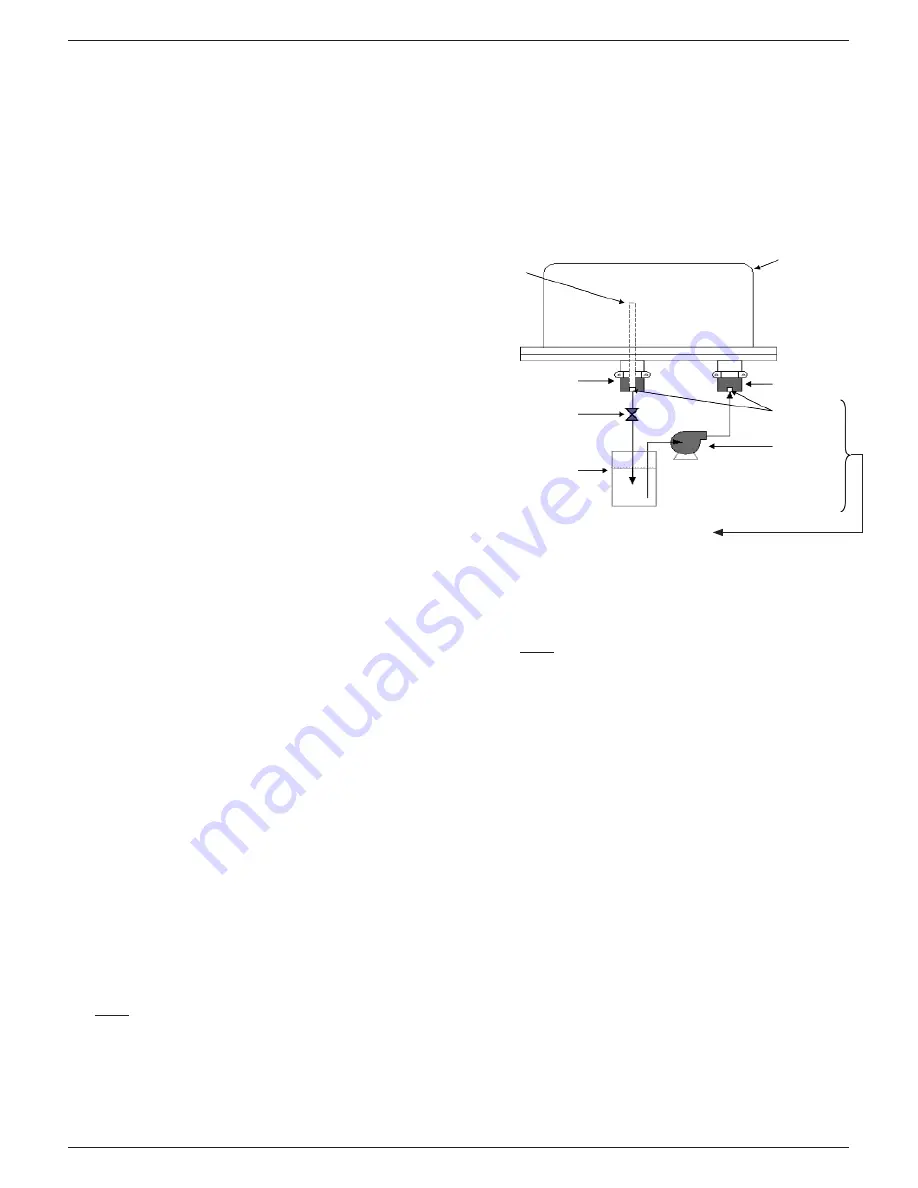
7. For proper cleaning, the acid must be pumped through
the exchanger in the direction shown in Fig 1 below.
The 3/8” nipple avoids gas pockets in the top of the
exchanger coil and must be on the outlet connection of
the cleaning system.
3/8” nipple must
be on return line
to acid reservoir
Heat Exchanger
Outlet
adaptor
3/8” or 1/2”
Globe Valve
Acid reservoir:
Oakite #32 or
similar acid
Intlet
adaptor
3/8” pipe
connections
Acid pump:
Jabasco,
Little Giant,
Calgon
or similar
Furnished
by customer
8. After cleaning is complete, the coil should be flushed
with water before reconnecting the manifolds.
Note:
For acid preparation, cleaning and safety
procedures, refer to the instructions supplied by the
acid manufacturer.
If Removal of the Coil is Necessary
1. Disconnect water piping and remove the manifold nuts
and lock rings.
2. Lift off the coil assembly (78 or 79), being careful not to
damage the manifold gaskets.
3.4 Re-assembly
Procedure
1. Replace manifold and baseplate gaskets.
2. Check that the tabs on the manifold lock rings fit into
the base plate slots. These keep the manifold-coil
assembly from turning when tightening the manifold
nuts.
3. Be sure the bottoms of the manifolds are seated in
pockets located inside the casing.
4. Install and tighten manifold nuts.
5. Install casing and tighten bolts sequentially.
6. Check nuts for tightness after an hour or two and again
after 24 hours of operation.
FIG. 1


