IM-P192-02
MI Issue 2
16
Upstream / downstream pipework
The TVA flowmeter should be installed in pipework manufactured to BS 1600, ASME B 36.10
Schedule 40 or EN 10216-2 / EN 10216-5 equivalent, which corresponds to the following
pipeline internal diameters:
For different pipe standards / schedules,
if the flowmeter is being operated at the
extreme of its published maximum
range, and maximum accuracy is
required, downstream spool pieces
manufactured from pipe to the above
standard should be used.
It is important that the internal upstream and downstream diameters of pipe are smooth.
Ideally seamless pipes should be used and there should be no intrusive weld beads on the
internal diameter. It is recommended that slip-on flanges be used to avoid any intrusive weld
beads on the internal diameter of the pipe.
Note:
See Figures 11 to 14 for other considerations which need to be noted before
determining the correct installation location.
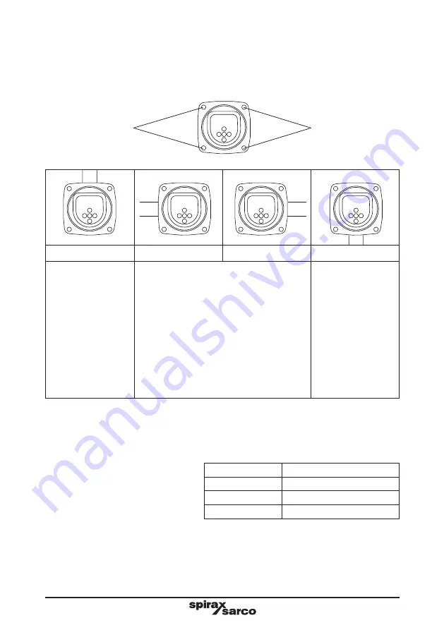
Rotating the electronics front panel
To rotate the electronics front panel loosen the four retaining screws and rotate the front
panel to the orientation, required.
Note:
Take care not to damage or strain any of the wiring.
A
B
C
D
For applications with
steam above 7 bar g
and all superheated
applications.
Note:
Fit ting the T VA
in this orientation
when the RS485
b o a r d i s f i t t e d
ensures that the
display can be read
easily.
For vertical flow applications.
For saturated steam
applications below
7 bar g.
Retaining screws
Retaining screws
Nominal diameter Nominal internal diameter
50 mm
52 mm
80 mm
77 mm
100 mm
102 mm


