SPT-N11U and SPT-N12U Chassis Installation Instructions
Powering the System
SPT-N11U and SPT-N12U Installation Instructions
|
15
P/N 71-008728 Rev A, August 2019
4
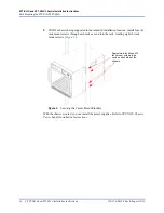
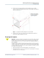
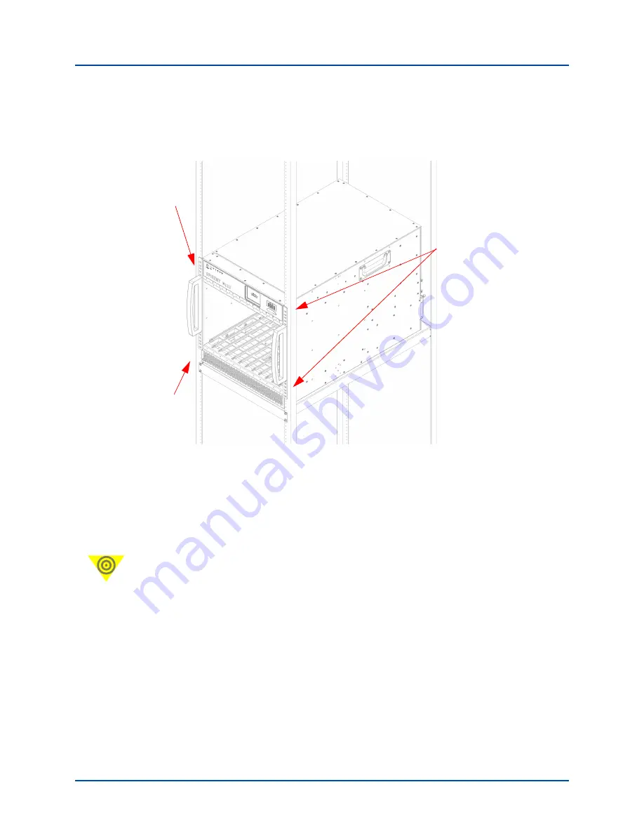
With the chassis being supported in the intended installation location, install a
minimum
of four (4) (recommended 8) rack mount screws through each front rack ear
and into the rack (
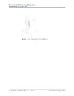
Figure 7.
Securing the Front-Mount Brackets to a Four-Post Shelf
5
With the chassis secured, you can install the power supplies. Refer to
SPT-N11U
Chassis Power Supply Installation Instructions.
Powering the System
Important:
Each power cord must be connected to a 15A circuit with no other connected
equipment and each with its own breaker. Installation of this chassis must comply with
local and national electrical codes. If necessary, consult with the appropriate agencies to
ensure compliance.
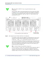
The Spirent SPT-N11U/SPT-N12U mainframe requires multiple circuits that require 100-
120 VAC or 200-240 VAC, 50 or 60 Hz, and 15A. These circuits are used to power fifteen
(15) power supplies (three system and twelve slot power supplies). The number of circuits
and voltage varies by system type:
•
SPT-N11U/SPT-N12U-220: Four (4) 200-240 VAC, 50 or 60 Hz, and 15A
•
SPT-N11U/SPT-N12U-110: Seven (7) 100-120 VAC, 50 or 60 Hz, and 15A; or, Seven
(7) 200-240 VAC, 50 or 60 Hz, and 6A.
Minimum 4 screw locations
shown here (recommended
8 locations are shown in


