DLS 400E3 Operating Manual
Spirent Communications - Page
2-5
7104000537 03/04 -2
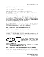
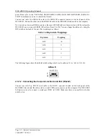
DLS 400E3 Back Panel Components
1)
Power Input
: for connecting to an AC power source
2)
Power Switch
: for turning power to the unit on or off
3)
Fuse box
: for fuse replacement when required
4)
IEEE 488 Address DIP Switch
: used to set a unique address for the unit
5)
Side A Line Bantam Jack:
used as an input/output connector
6)
Side A External Noise IN BNC Connector
: used to insert noise from an external source
7)
RS–232 (DCE) Serial Connector
: for connection to a computer for remote control
8)
IEEE 488 Connector:
for connection to a computer for remote control
2.5.5
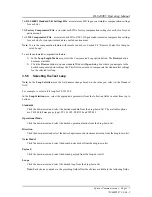
Connecting to Power
Each of the two DLS 400E3 chassis are built with a 2-fuse configuration. Please refer to Chapter 12
"SAFETY" for more details.
Connect the power input which can be found at the back of each of the two DLS 400E3 chassis to an AC
line, voltage between 100 and 240 V
RMS
+/-10% and a frequency of 50 to 60 Hz. The DLS 400E3 can work
with any voltage and frequency in this range, switch settings are not required.
The DLS 400E3 always powers-up in an "idle" state. When powered off, the DLS 400E3 remains latched to
the previously selected loop settings, allowing the unit to be used when power is turned off.
Note:
If the unit is powered off, internal noise generators will not output.
2.5.6
Injecting Noise in the System
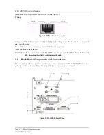
You can inject externally-generated impairments using the CF or RJ45 connectors on the front of the
DLS 400E3. An external noise impairment generator can be purchased which can inject noise differentially
onto the wireline with a 4 KOhm Thevenin output impedance.
The DLS 400E3 also has (2) 50 Ohm BNC external noise inputs located on the rear panel. These inputs are
labelled as side A and B and can be used to inject noise when a DLS 5A01H noise card(s) are installed in the
noise card slots within the wireline chassis, this allows differential noise injection from external noise injec-
tion products.
The DLS 5200E3 Noise Generation System can generate both user-defined and pre-packaged noise shapes
from DC to 12 MHz. It provides convenient noise injection circuitry. For more information on the
DLS 5200E3 product, see the
DLS 5200E3Operating Manual
.
2.5.7
Connecting to a Windows Computer (for Remote Control)
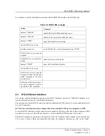
You configure the DLS 400E3 wireline simulator remotely via a computer connected to either an IEEE 488
or an RS-232 interface on the rear panel of the simulator. There are two options available to control the
DLS 400E3, one being Spirent Communications’s DLS 400E3 Software, or the second being custom soft-
ware / scripting using commands sets.
The DLS 400E3 Software allows you to select simulated or external jack termination for bridged taps, as
well as the type of calibration loop simulated. If you are developing custom control software, refer to Chap-
ter 4 "COMMON COMMAND SET FOR REMOTE CONTROL"and Chapter 6 "DEVICE SPECIFIC
COMMANDS FOR REMOTE CONTROL" which discuss the accepted commands to configure the unit.
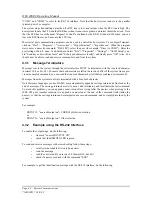
2.5.7.1 Connecting the Computer via the IEEE 488 Port (GPIB)
The IEEE 488 portion of the control software supplied by Spirent Communications only works with a
National™ IEEE 488 interface card. If necessary, install the National™ IEEE 488 interface card in the com-
Summary of Contents for DLS 400E3
Page 1: ...Operating Manual DLS 400E3 ADSL European Wireline Simulator Revision 2 March 2004...
Page 2: ......
Page 10: ...DLS 400E3 Operating Manual Page 1 6 Spirent Communications 7104000537 03 04 2...
Page 52: ...DLS 400E3 Operating Manual Page 7 2 Spirent Communications 7104000537 03 04 2...
Page 56: ...DLS 400E3 Operating Manual Page 9 2 Spirent Communications 7104000537 03 04 2...
Page 58: ...DLS 400E3 Operating Manual Page 10 2 Spirent Communications 7104000537 03 04 2...
Page 64: ...DLS 400E3 Operating Manual Page 12 4 Spirent Communications 7104000537 03 04 2...


