background image

Customer Service 1-888-707-1880 


Dyaco Canada Inc. 2016 

Email: customerservice@dyaco.ca 

33 


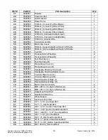
KEY # 

PART # 

Part description 

Q'ty 

41 

6048541 

Breaker 

42 

6048542 

Power Socket 

43 

6048543 

On/Off Switch 

44 

6048544 

Power Cord 

45 

6048545 

100m/m_Connecting Wire (Black) 

46 

6048546 

350m/m_Connecting Wire (White) 

47 

6048547 

350m/m_Connecting Wire (Black) 

48 

6048548 

800m/m_Computer Cable (Upper) 

49 

6048549 

1200m/m_Computer Cable(Lower) 

50 

6048550 

1250m/m_Computer Cable(Middle) 

51 

6048551 

1000m/m_Ground Wire 

52 

6048552 

Console Assembly 

53 

6048553 

Motor Top Cover 

54 

6048554 

300m/m_Speed Adjustment Switch W/Cable 

55 

6048555 

300m/m_Incline Adjustment Switch W/Cable 

56 

6048556 

Cushion 

57 

6048557 

Transportation Wheel(A) 

58 

6048558 

Transportation Wheel(B) 

59 

6048559 

Foot Rail Cap (L) 

60 

6048560 

Foot Rail Cap (R) 

61 

6048561 

Frame Base Cover (L) 

62 

6048562 

Frame Base Cover (R) 

63 

6048563 

Handpulse End Cap Top Cover 

64 

6048564 

Handpulse End Cap Bottom Cover 

66 

6048566 

Console Mast Cover (L) 

67 

6048567 

Console Mast Cover (R) 

68 

6048568 

Rear Adjustment Base (L) 

69 

6048569 

Rear Adjustment Base (R) 

70 

6048570 

Motor Cover Anchor(D) 

71 

6048571 

Ø24 × Ø10 × 3T_Nylon Washer (A) 

72 

6048572 

Ø50 × Ø13 × 3T_Nylon Washer (B) 

73 

6048573 

Adjustment Foot Pad 

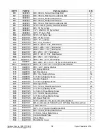
75 

6048575 

Quadrate Safety Key 

77 

6048577 

Wheel Sleeve 

79 

6048579 

Aluminum Foot Rail 

80 

6048580 

1/2" × 1-1/4"_Carriage Bolt 

81 

6048581 

1/2" × 1"_Hex Head Bolt 

82 

6048582 

3/8" × 4-1/2"_Socket Head Cap Bolt 

83 

6048583 

3/8" × 3-3/4"_Button Head Socket Bolt 

84 

6048584 

3/8" × UNC16 × 1-1/2"_Hex Head Bolt 

85 

6048585 

3/8" × 1-1/4"_Hex Head Bolt 

86 

6048586 

3/8" × 2"_Flat Head Socket Bolt 

87 

6048587 

5/16" × 1"_Button Head Socket Bolt 

88 

6048588 

5/16" × 2-3/4"_Button Head Socket Bolt 

89 

6048589 

M8 × 60m/m_Hex Head Bolt 

Summary of Contents for 16007604850-1

Page 1: ...Retain For Future Reference Owner s Manual Model No 16007604850 1 XT485 Assembly Operation Adjustments Parts Warranty CAUTION Read and understand this manual before operating unit...

Page 2: ...4 Important Electrical Instructions 6 Assembly Instructions 8 Folding Transportation Instructions 13 Operation of Your New Treadmill 14 Using the Spirit Fit App 18 Programmable Features 19 Target Hear...

Page 3: ...u with the technical knowledge and service personnel to make your experience more informed and any difficulties easier to remedy Please take a moment at this time to record the name of the dealer thei...

Page 4: ...cated circuit 2 It is the responsibility of the owner to ensure that all users of this treadmill are adequately informed of all warnings and precautions 3 The use of an extension cord with this produc...

Page 5: ...Always use proper lifting techniques You must not use any attachments that are not recommended by the manufacturer 21 Use the treadmill only for its intended use as described in this manual Do not use...

Page 6: ...of least resistance for electric current reducing the risk of electric shock This product is equipped with a cord having an equipment grounding plug The plug must be plugged into an appropriate outle...

Page 7: ...l portion of the console control head Your treadmill will not start and operate without this Removing the magnet also secures the treadmill from unauthorized use 2 Fasten the plastic clip onto your cl...

Page 8: ...the treadmill s folding mechanism to spring open If the end of the Velcro strap that you need to grab to remove it happens to be under the treadmill deck reach under the deck to grab it but do not ti...

Page 9: ...IGHT 4 and attach the MIDDLE COMPUTER CABLE 50 to the LOWER COMPUTER CABLE 49 Be careful not to pinch the cable or damage may occur to the system 6 Slide the right upright 4 to sit into the frame base...

Page 10: ...ABLE 55 with the UPPER INCLINE CABLE 38 4 Connect the MIDDLE COMPUTER CABLE 50 to the UPPER COMPUTER CABLE 48 5 Be sure not to pinch any of the cables or damage may occur to the system 6 Insert the CO...

Page 11: ...ail customerservice dyaco ca 11 STEP 3 1 Gather HARDWARE FOR STEP 3 2 Install FRAME BASE COVER RIGHT AND LEFT 62 61 onto the FRAME BASE 2 using 6 Tapping Screws 120 Tighten with the PHILLIPS HEAD SCRE...

Page 12: ...PHILLIPS HEAD SCREWDRIVER 148 4 Place the HANDRAIL SUPPORT 119 between the LEFT AND RIGHT UPRIGHTS 5 4 and use the 5 COMBINATION ALLEN WRENCH PHILLIPS HEAD SCREWDRIVER 131 to tighten 4 BUTTON HEAD SOC...

Page 13: ...the treadmill running deck until it is secured by the locking telescoping tube assembly in center back of base TO UNFOLD THE TREADMILL Apply slight forward pressure on the treadmill running deck with...

Page 14: ...ine then select either 2 or 3 digits and the treadmill will automatically adjust to that value This saves time because you don t have to press and hold or hold a button down until reaching the desired...

Page 15: ...h located to the right of the LCD screen will show your current heart rate in relation to your projected maximum heart rate which is determined by your Age that you entered during the programming phas...

Page 16: ...Stop key once This will slowly decelerate the tread belt to a stop The incline will go to zero percent The Time Distance and Calorie readings will hold while the unit is in the pause mode After 5 minu...

Page 17: ...your Age and Weight Entering your Age is necessary during the Heart Rate programs to ensure the correct predicted target heart rate zone Entering your Weight aides in calculating a more correct Calor...

Page 18: ...sync your workout data with one of many fitness cloud sites we support iHealth MapMyFitness Record or Fitbit with more to come Syncing the App with your exercise machine 1 Download the App 2 Open the...

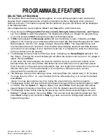
Page 19: ...The Message center will now be blinking a value indicating your Body Weight default is 150 lbs 70kgs Entering the correct bodyweight will affect the calorie count Use the or keys to adjust then press...

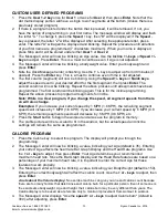
Page 20: ...ming Repeat the above process to program all segments for incline Note While in a User program if you change the speed all segment speeds from there on will also change Examples If you increase your c...

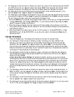
Page 21: ...5 Entering your correct Age affects the heart rate Bar Graph Display and the Heart Rate programs Use the speed or keys to adjust then press Enter Your Age determines your recommended maximum heart rat...

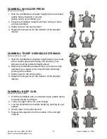
Page 22: ...2MPH KPH and 1 00 3MPH KPH 1st cardio interval begins lasting 0 30 console counts down to 0 00 and the Message Center displays STRENGTH INTERVAL 1 BEGIN DUMBBELL ROW User steps off of the treadmill to...

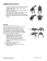
Page 23: ...UP EMPHASIS CHEST SHOULDERS BACK OF ARMS There are two variations of this exercise If you aren t able to perform the exercise as shown in this illustration place your knees on the floor a padded mat o...

Page 24: ...ells at shoulder height behind your head with a neutral grip palms facing one another your elbows should be pointed straight ahead 2 Raise the dumbbells overhead until your arms are fully extended you...

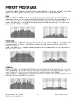
Page 25: ...orkout and lasts for 10 of the duration FAT BURN Resistance This program follows a quick progression up to the maximum speed level default or user input level that is sustained for 2 3 of the workout...

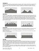
Page 26: ...roughout this program The incline alternates between 25 65 of maximum elevation CALORIES Resistance This program follows a quick progression up to the maximum speed level default or user input level t...

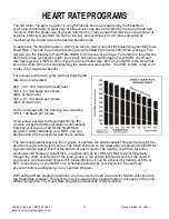
Page 27: ...180 maximum heart rate 180 x 6 108 beats per minute 60 of maximum 180 x 8 144 beats per minute 80 of maximum So for a 40 year old the training zone would be 108 to 144 beats per minute If you enter yo...

Page 28: ...e Borg scale is as follows Rating Perception of Effort 6 Minimal 7 Very very light 8 Very very light 9 Very light 10 Very light 11 Fairly light 12 Comfortable 13 Somewhat hard 14 Somewhat hard 15 Hard...

Page 29: ...transmitter directly on bare skin assures you of proper operation If you wish you may wear the transmitter over a shirt To do so wet the areas of the shirt that the electrodes will rest upon Note The...

Page 30: ...to enter your Weight You may adjust the weight value using the Speed or keys then press Enter to continue 4 Next is Time You may adjust the time using the Speed or keys and press Enter to continue 5...

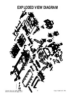
Page 31: ...Customer Service 1 888 707 1880 Dyaco Canada Inc 2016 Email customerservice dyaco ca 31 EXPLODED VIEW DIAGRAM...

Page 32: ...048520 Drive Belt 1 21 6048521 Front Roller W Pulley 1 21 3 6048521 3 Magnet 2 22 6048522 Rear Roller 1 23 6048523 Running Deck 1 24 6048524 Running Belt 1 25 6048525 PVC Handgrip 2 26 6048526 Deck Cr...

Page 33: ...l Cap L 1 60 6048560 Foot Rail Cap R 1 61 6048561 Frame Base Cover L 1 62 6048562 Frame Base Cover R 1 63 6048563 Handpulse End Cap Top Cover 2 64 6048564 Handpulse End Cap Bottom Cover 2 66 6048566 C...

Page 34: ...1 110 1 60485110 1 6 5 16 1 0T_Flat Washer 4 111 60485111 6 23 13 5 5T 3T_Nylon Dished Washer 4 112 1 60485112 1 5 5 27 60 1 5T 3 5H_Concave Washer 4 113 60485113 10 2 0T_Spring Washer 8 114 60485114...

Page 35: ...Part description Q ty 140 60485140 Handgrip End Cap 2 141 60485141 5 1 5T_Spring Washer 4 142 60485142 3 5 16m m_Sheet Metal Screw 8 145 60485145 400m m_Audio Cable 1 148 60485148 Phillips Head Screw...

Page 36: ...ood and vacuum out dirt that may accumulate UNPLUG POWER CORD BEFORE THIS TASK BELT ADJUSTMENTS Tread belt Tension Adjustment Belt tension is not critical for most users It is very important for jogge...

Page 37: ...TREADBELT TRACKING A 6 mm Allen wrench is provided to adjust the rear roller Make tracking adjustments from the left side only Set belt speed at approximately 2 to 3 MPH A small adjustment can make a...

Page 38: ...the 6 mm Allen wrench supplied loosen the two rear roller adjustment bolts located in the rear end caps enough to get your hand under the belt 5 10 turns Make sure to loosen both bolts the same amount...

Page 39: ...walking pattern is natural track the belt slightly off center to the side opposite from the belt movement See General Maintenance section on Tread belt Tension Adjust as necessary 1 If the belt moves...

Page 40: ...to it 3 Make sure the sensor is as close as possible to the pulley without touching it You will see a magnet on the face of the pulley make sure the sensor is aligned with the magnet There is a screw...

Page 41: ...income producing purpose or 2 subject to misuse neglect accident or unauthorized repairs and alterations This warranty provided herein is in lieu of all other express warranties Any implied warrantie...

Page 42: ...and products manufactured and distributed by Dyaco Canada Inc spiritfitness ca solefitness ca xterrafitness ca dyaco ca products everlast html dyaco ca UFC UFC home html spiritfitness ca johnnyg html...

Reviews: