background image

Customer service   1-888-707-1880


Dyaco Canada Inc 2013. 

Email:  customerservice@dyaco.ca 


41 


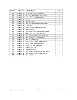
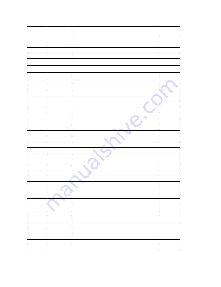
KEY NO   

PART NO    DESCRIPTION   

QTY   

42 

1660542 

Handgrip Side Cap(Top)   

43 

1660543 

Handgrip Side Cap (Bottom) 

44 

1660544 

Hall Sensor Rack   

45 

1660545 

Pedal

L


46 

1660546 

Pedal

R


47 

1660547 

Transportation Wheel   

49 

1660549 

1"_Button Head Plug   

50 

1660550 

3/8" × 2-1/4"_Hex Head Bolt   

51 

1660551 

5/16" × 5/8"_Hex Head Bolt   

52 

1660552 

5 × 19m/m_Tapping Screw   

53 

1660553 

5/16" × 1-3/4"_Button Head Socket Bolt   

54 

1660554 

1/4" × 3/4"_Hex Head Bolt 

55 

1660555 

M8 × 170m/m_J Bolt 

56 

1660556 

M6 × 15m/m_Phillips Head Screw   

57 

1660557 

3/16" × 15 × 1.5T_Flat Washer   

58 

1660558 

M5 × 12m/m_Phillips Head Screw   

12 

59 

1660559 

3/8" × 2m/m_Flat Head Socket Bolt 

61 

1660561 

5 × 16m/m_Tapping Screw 

62 

1660562 

Ø3 × 20m/m_Tapping Screw   

63 

1660563 

Ø3.5 × 16m/m_Sheet Metal Screw   

64 

1660564 

Ø3.5 × 20m/m_Sheet Metal Screw   

65 

1660565 

Ø3 × 10m/m_Tapping Screw   

66 

1660566 

Ø17_C Ring 

67 

1660567 

Ø20_C Ring   

69 

1660569 

1/4" × 13 × 1T_Flat Washer 

70 

1660570 

3/8" × 19 × 1.5T_Flat Washer 

71 

1660571 

3/8" × 25mm × 2.0T_Flat Washer 

72 

1660572 

5/16" × 18mm × 1.5T_Flat Washer 

73 

1660573 

Ø17 × 23.5 × 1T_Flat Washer   

76 

1660576 

Ø1/4"_Split Washer   

77 

1660577 

M8 × 7T_Nyloc Nut   

78 

1660578 

3/8" × 7T_Cap Nut 

79 

1660579 

1/4" × 8T_Nyloc Nut   

80 

1660580 

5/16" × 6T_Nyloc Nut   

82 

1660582 

3/8" × 7T_Nut   

83 

1660583 

M10 × 1.25_ Nut 

85 

1660585 

Round Disk   


Summary of Contents for 16116605 CU800

Page 1: ...Retain For Future Reference Owner s Manual Model No 161168800 CR800 16116605 CU800 Assembly Operation Adjustments Parts Warranty CAUTION Read and understand this manual before operating unit...

Page 2: ...on 4 Important Operation Instructions 4 CR800 161168800 Instructions 5 CU800 16116605 Instructions 12 Features 18 Operation of Your New Bike 19 Maintenance 33 161168800 CR800 Part list and diagram 34...

Page 3: ...culties easier to remedy Please take a moment at this time to record the name of the dealer their telephone number and the date of purchase below to make any future needed contact easy We appreciate y...

Page 4: ...ay from heated surfaces Never drop or insert any object into any openings Do not use outdoors To disconnect turn all controls to the off position then remove the plug from the outlet Do not attempt to...

Page 5: ...is producing A C power while the bike is being used Do not service the bike while the generator is spinning Serious electric shock could occur NEVER expose the bike to rain or moisture This product is...

Page 6: ...1168800 CR800 Step 1 77 3 8 X 3 4 Flat Washer 6 pcs 84 3 8 X 1 Flat Washer 4 pcs 71 3 8 x 2 Hex Head Bolt 4 pcs 89 3 8 Nylon Nut 6 pcs Step 2 136 M5 x 15mm Phillips Head Screw 4 pcs 77 3 8 x 3 4 Flat...

Page 7: ...ce dyaco ca 6 Step 3 68 5 16 x 5 8 Hex Head Bolt 8 pcs 83 5 16 X 3 4 Curved Washer 2 pcs 76 5 16 X 11 16 Flat Washer 6 pcs 82 5 16 Split Washer 2pcs Step 4 105 4mm x 16mm Self Tapping Screw 4 pcs 98 M...

Page 8: ...Customer service 1 888 707 1880 Dyaco Canada Inc 2013 Email customerservice dyaco ca 7 Tools 114 Phillips Screw Driver 1 pc 112 12 14mm Wrench 1 pc 132 14 15mm Wrench 1 pc...

Page 9: ...the seat carriage 4 with four 3 8 X 2 bolts 71 installed through the top holes and secured with four 3 8 flat washers 77 and 3 8 nylon nuts 89 Install two 3 8 X 2 3 4 bolts 175 through the side holes...

Page 10: ...ustomerservice dyaco ca 9 STEP 2 SEAT BACK 4 Install Seat Back Frame 5 onto the Seat Carriage 4 with six 3 8 x 3 4 Hex Head bolts 176 and 3 8 x 3 4 flat washers 77 5 Install the Seat Back Cover 128 on...

Page 11: ...through the bottom of the console mast tube and out the top opening 2 Slide the console mast into the receiving tube 1 being careful to not pinch the wires Fasten the console mast with six 5 16 x 5 8...

Page 12: ...er that the left pedal has a reverse thread and will be screwed into the crank in the opposite rotation from normal threads There is an L stamped into the end of the threaded post of the left pedal an...

Page 13: ...05 CU800 Step 1 71 3 8 X 25 Flat Washer 4pcs 50 3 8 x 2 1 4 Hex Head Bolt 4pcs Step 2 51 5 16 x 5 8 Hex Head Bolt 7pcs 99 5 16 X 19 Curved Washer 1pcs 72 5 16 X 18 Flat Washer 6pcs Step 3 51 5 16 x 5...

Page 14: ...Customer service 1 888 707 1880 Dyaco Canada Inc 2013 Email customerservice dyaco ca 13 Tools 93 Phillips Screw Driver 1pc 100 12 14mm Wrench 1pc 117 13 15mm Wrench 1pc...

Page 15: ...707 1880 Dyaco Canada Inc 2013 Email customerservice dyaco ca 14 STEP 1 REAR STABILIZER ASSEMBLY 1 Install the Rear Stabilizer 5 onto the Main Frame 1 with the four 3 8 x 2 1 4 Hex Head Bolts 50 and f...

Page 16: ...Mast Cover 38 and the Console Mast 2 until the cable connector comes out the top opening of the console mast Slide the plastic cover 38 onto the console mast ensuring the correct orientation of the co...

Page 17: ...Run the two hand pulse wires 26 into the hole in the handle bar mounting plate and out through the hole in the console plate Install the Handle Bar 3 onto the Console Mast 2 with two 5 16 x 5 8 Hex H...

Page 18: ...als 45 L 46R onto the Crank arms 16L 16R Remember that the left pedal has a reverse thread and will be screwed into the crank in the opposite rotation from normal threads There is an L stamped into th...

Page 19: ...the pedals this width between the pedals is called the Q factor Spirit has designed our pedal system so the Q factor is the smallest in the industry but we did not stop there We have also custom desig...

Page 20: ...for a short time When the lights go off the dot matrix display will show a software version i e VER 1 0 and the message window will display an odometer reading The odometer reading displays how many...

Page 21: ...n a program the dot matrix will display the workout Profile To the left of the dot matrix there is a button labeled Display Pressing this button once will switch the display to show a quarter mile tra...

Page 22: ...s a Number Key Pad when you are in the data setup mode Under each program key is a number If you are setting new data such as Age weight etc you can use these keys to enter the numbers quickly The con...

Page 23: ...matically starts you at level one This is the easiest level and it is a good idea to stay at level one for a while to warm up If you want to increase the work load at any time press the Up key the Dow...

Page 24: ...gram does not use heart rate but simulates a lower steady exertion workout Work Profile Cardio The Cardio program is designed to increase your Cardio vascular function This is exercise for your heart...

Page 25: ...ion level you will experience during the program at the top of the hill Adjust the level and then press enter 6 Now you are finished editing the settings and can begin your workout by pressing the Sta...

Page 26: ...ou may adjust the Weight number using the Up and Down keys or the numeric key pad then press enter to continue 5 Next is Time You may adjust the Time and press enter to continue 6 Now you are asked to...

Page 27: ...aveats are that if you are a very de conditioned Male you need to choose option Female If you are a very conditioned female you need to choose option Male Workload chart for male or very fit female 1s...

Page 28: ...the test Hold the hand grips gently do not tense up During the test The console must be receiving a steady heart rate for the test to begin You may use the hand pulse sensors or wear a heart rate ches...

Page 29: ...46 40 42 35 38 32 35 30 31 26 28 below average 37 41 35 39 31 34 29 31 26 29 22 25 poor 30 36 30 34 26 30 25 28 22 25 20 21 very poor 30 30 26 25 22 20 VO2max Chart for females and de conditioned male...

Page 30: ...ts per minute 60 of maximum 180 X 8 144 beats per minute 80 of maximum So for a 40 year old the training zone would be 108 to 144 beats per minute If you enter your age during programming the console...

Page 31: ...The scale is as follows Rating Perception of Effort 6 Minimal 7 Very very light 8 Very very light 9 Very light 10 Very light 11 Fairly light 12 Comfortable 13 Somewhat hard 14 Somewhat hard 15 Hard 16...

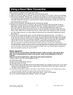
Page 32: ...ngs Wearing the transmitter immediately against bare skin assures you of proper operation If you wish you may wear the transmitter over a shirt To do so moisten the areas of the shirt that the electro...

Page 33: ...E At any time during the editing of Data you can press the Stop key to go back one level or screen 7 If you want to increase or decrease the workload at any time during the program press the Up or Dow...

Page 34: ...le has built in maintenance diagnostic software The software will allow you to change the console settings from English to Metric and turn off the beeping of the speaker when a key is pressed for exam...

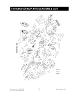
Page 35: ...Customer service 1 888 707 1880 Dyaco Canada Inc 2013 Email customerservice dyaco ca 34 161168800 CR800 PARTS DIAGRAM LIST...

Page 36: ...te 3 14 16880014 Aluminum Axle 1 15 16880015 Rack 1 16 16880016 Spacer for Stopper Axle 4 17 16880017 Rubber Foot 2 18 16880018 Transportation Wheel 2 19 16880019 Console Assembly 1 20 16880020 Drive...

Page 37: ..._Bearing 2 54 16880054 Drive Belt 1 55 16880055 Induction Brake 1 56 16880056 Magnet 1 61 16880061 Seat 1 63 16880063 Seat Back 1 64 16880064 Handgrip Foam 2 65 16880065 3 8 2 1 4 _Hex Head Bolt 4 66...

Page 38: ...Spring 1 105 168800105 4 16 m m_Sheet Metal Screw 4 106 168800106 5 16 1 3 4 _Button Head Socket Bolt 2 107 168800107 3 5 20m m_Sheet Metal Screw 3 108 168800108 M10 1 25_Nut 2 109 168800109 3 8 7T_N...

Page 39: ...00167 Seat Front Aft Adjustment Lever 1 168 168800168 Lever Anchor 1 169 168800169 M5 25m m_Flat Head Socket Screw 2 170 168800170 15 6 4T_Nylon Washer 1 171 168800171 M5 45m m_Socket Head Cap Bolt 1...

Page 40: ...Customer service 1 888 707 1880 Dyaco Canada Inc 2013 Email customerservice dyaco ca 39 16116605 CU800 PARTS DIAGRAM LIST...

Page 41: ...660516R Crank Arm R 1 17 1660517 Bearing for Crank Axle 2 18 1660518 Bearing for Idler Arm 2 19 1660519 Seat 1 20 1660520 Induction Brake 1 21 1660521 Controller 1 22 1660522 Magnet 1 23 1660523 Hall...

Page 42: ...s Head Screw 3 57 1660557 3 16 15 1 5T_Flat Washer 1 58 1660558 M5 12m m_Phillips Head Screw 12 59 1660559 3 8 2m m_Flat Head Socket Bolt 4 61 1660561 5 16m m_Tapping Screw 6 62 1660562 3 20m m_Tappin...

Page 43: ...1660599 5 16 19 1 5T_Curved Washer 1 100 16605100 12 14m m_Wrench 1 102 16605102 5 16 16 1 0T_Flat Washer 3 103 16605103 5 16 _Split Washer 2 105 16605105 Front Handle Bar Cover 1 106 16605106 Seat U...

Page 44: ...ss for particular purpose are limited in duration to the first 24 months from date of purchase All other obligations or liabilities including liability for consequential damages are hereby excluded RE...

Reviews: