background image

                                                                            EL7 Elliptical


12


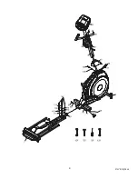
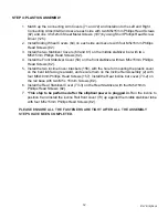
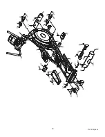
STEP 4: PLASTICS ASSEMBLY 
 

1.  Match up the Connecting Arm Covers (71 and 72) and install onto the Left and Right 

Connecting Arms (8&9) and secure each side with two M5x15mm Phillips Head Screws 
(82) and one 3.5x12mm Sheet Metal Screws (107) by using Short Phillips Head Screw 
Driver (125). 

2.  Install Sliding Wheel Covers (64) on each side and secure with four M5x15mm Phillips 

Head Screws (82). 

3.  Install the two Stabilizer Covers (60 and 61) on the middle stabilizer bar with two 

M5x15mm Phillips Head Screws (82). 

4.  Install the Front Stabilizer Cover (59) on the front stabilizer with two M5x15mm Phillips 

Head Screws (82). 

5.  Install the two incline Cover brackets (156), with the hole for mounting the plastic cover 

on the bent tab facing rearward, and secure them on the Incline Rail Assembly (2) with 
four M6x10mm Phillips Head Screws (157). Install the Rear incline bar cover (73-2) on 
the rail base with two M5 x 15m/m Screws (82). 

6.  Install the Rear Stabilizer Cover (73-3) on the Rear Stabilizer with four M5x15mm 

Phillips Head Screws (82). 

7. 

*This step to be performed after the elliptical power is plugged in.

 Run the incline to 

position 8 and install the incline Rail front cover (73) up against the middle stabilizer tube 
with four M5x15mm Phillips Head Screws (82). 


PLEASE ENSURE ALL THE FASTENERS ARE TIGHT AFTER ALL THE ASSEMBLY 
STEPS HAVE BEEN COMPLETED. 

Summary of Contents for EL7

Page 1: ...Z100 Z300 Z500 Z700 OWNER S MANUAL PLEASE CAREFULLY READ THIS ENTIRE MANUAL BEFORE OPERATING YOUR NEW ELLIPTICAL ...

Page 2: ...Registration 2 Important Safety Instructions 3 Important Electrical Information 4 Important Operation Instructions 4 Assembly Instructions 5 Operation of Your New Elliptical 15 Manufacturer s Limited Warranty 27 EL7 Elliptical 1 ...

Page 3: ...nd the date of purchase below to make any future needed contact easy We appreciate your support and we will always remember that you are the reason that we are in business Please complete and mail your registration card today and enjoy your new elliptical Yours in Health Spirit Manufacturing Inc Name of Dealer_______________________________________________ Telephone Number of Dealer_______________...

Page 4: ...e motor could ignite a highly gaseous environment Never drop or insert any object into any openings Do not use outdoors To disconnect turn all controls to the off position then remove the plug from the outlet Do not attempt to use your elliptical for any purpose other than for the purpose it is intended The hand pulse sensors are not medical devices Various factors including the user s movement ma...

Page 5: ...d malfunction or breakdown grounding provides a path of least resistance for electric current reducing the risk of electric shock This product is equipped with a cord having an equipment grounding plug The plug must be plugged into an appropriate outlet that is properly installed and grounded in accordance with all local codes and ordinances DANGER Improper connection of the equipment grounding co...

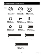
Page 6: ...c 76 3 8 x 3 4 Hex Head Bolt 2pcs 100 5 16 x 20x 1 5T Flat Washer 4 pcs 89 3 8 x 7T Nylon Nut 2 pcs 85 M5x10m m 167 5 16 x 2 1 4 Hex Head Bolt 4 pcs 77 3 8 x 1 1 2 Hex Head Bolt 2pcs 178 Ø5 16 x 1 5T Split Washer 4pcs 179 Ø5 16 Star Washer 4pcs Phillips Head Screw 4 pcs Step 1 75 3 8 x 2 1 4 Hex Head Bolt 1pc EL7 Elliptical 5 ...

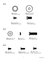
Page 7: ...er 2 pcs 131 3 8 x 30 x 2 0T Flat Washer 2 pcs 107 3 5x12m m Sheet Metal Screw 2pcs 82 M5 x 15m m Phillips Head Screw 22pcs 157 M6 x 10m m Phillips Head Screw 4 pcs 100 5 16 x 20 x 1 5T Flat Washer 2 pcs 79 5 16 x 1 1 4 Hex Head Bolt 2 pcs 91 5 16 x 7T Nylon Nut 2 pcs Step 3 Step 4 EL7 Elliptical 6 ...

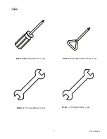
Page 8: ...Tools 126 Phillips Screw Driver 1 pc 125 Short Phillips Screw Driver 1 pc 129 12 14 m m Wrench 1 pc 124 13 14m m Wrench 1 pc EL7 Elliptical 7 ...

Page 9: ...k color codes of the wires 37 and the 3 pin position Sensor Connector 38 Locate the Console Mast 12 and Console Mast Cover 49 and slide the Cover onto the Mast as far as it will go Make sure the Console Mast Cover is facing the correct way At the top opening of the Main Frame of the elliptical there is a Computer Cable 39 and an incline cable 36 Unravel and straighten out the cables and feed them ...

Page 10: ...EL7 Elliptical 9 ...

Page 11: ... a small sticker on them indicating L left and R right 3 Install two 3 8 X 35 mm Flat Washers 131 onto the two 3 8 X 3 4 Hex Head Bolts 76 and install and tighten in the threaded holes in the ends of the axle 4 Install the Front Handle Bar Covers 68 left 69 right and Rear Handle Bar Covers 68 1 left 69 1 right over the Handle Bar axle connections and secure with the six 3 5x10m m Sheet Metal Screw...

Page 12: ...g arms 8 9 Align the hole in the rod ends with the hole in the brackets of the left and right Handle Bar 10 11 The rod end should be on the inside of the Handle Bar bracket Secure both sides with a 5 16 x1 1 4 Hex Head Bolt 79 5 16 x20mm Flat Washer 100 and 5 16 Nylon Nut 91 by using 13 14 mm Wrench 124 and 12 14 mm Wrench 129 EL7 Elliptical 11 ...

Page 13: ...bilizer with two M5x15mm Phillips Head Screws 82 5 Install the two incline Cover brackets 156 with the hole for mounting the plastic cover on the bent tab facing rearward and secure them on the Incline Rail Assembly 2 with four M6x10mm Phillips Head Screws 157 Install the Rear incline bar cover 73 2 on the rail base with two M5 x 15m m Screws 82 6 Install the Rear Stabilizer Cover 73 3 on the Rear...

Page 14: ...59 82 82 107 72 71 82 82 64 82 EL7 Elliptical 13 ...

Page 15: ...econd solution was to make the foot pedal adjustable to the user s style of pedaling the elliptical We achieved this by adding an adjustment that allows the angle of the footpad to be changed Because everybody is different and there are as many styles to pedal an elliptical as there are people we found there is no one angle that fit every user Some users would be up on the balls of their feet resu...

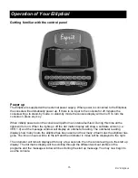
Page 16: ...s will turn on When the lights go off the dot matrix display will show a software version i e VER 1 0 and the message window will display an odometer reading The odometer reading displays how many hours the elliptical has been used and how many virtual miles the elliptical has gone The time in hours will be to the left and the odometer in miles will be displayed to the right The odometer will rema...

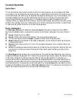
Page 17: ...er Minute This is the actual pedal speed z L Current Work Level and MaxL Maximum Work Level of the program z Watts Indication of workload If 100 watts is displayed you are doing enough work to keep a 100 watt light bulb lit z Ramp Shows incline level from 1 to 20 The dot matrix will switch to the incline profile at the same time z Scan the message window will show each set of data for four seconds...

Page 18: ...ill be asked for your Age and Weight Entering your Age is necessary during the Heart Rate control programs to ensure the correct settings are in the program for your Age Otherwise the work settings could be too high or low for you Entering your weight aids in calculating a more correct calorie reading Although we cannot provide an exact calorie count we do want to be as close as possible A message...

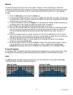
Page 19: ...er key NOTE At any time during the editing of Data you can press the Stop key to go back one level or screen 6 Once the program starts you will be at level one This is the easiest level and it is a good idea to stay at level one for a while to warm up If you want to increase the work load at any time press the Up key the Down key will decrease the work load 7 During the Manual program you will be ...

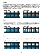
Page 20: ...Work Profile Incline Profile Cardio The Cardio program is designed to increase your Cardio vascular function This is exercise for your heart and lungs It will build up your heart muscle and increase blood flow and lung capacity This is achieved by incorporating a higher level of exertion with slight fluctuations in work Work Profile Incline Profile Strength The Strength program is designed to incr...

Page 21: ...or off the Incline profile You can choose to turn the incline profile off and just use the Incline switches on the console to manually control the incline angle setting during the program 7 Now you are finished editing the settings and can begin your workout by pressing the Start key You can also go back and modify your settings by pressing the Stop key to go back one level or screen 8 If you want...

Page 22: ...essage window will ask you to enter your Age You may enter your Age using the Up and Down keys or the numeric key pad then press the Enter key to accept the new number and proceed on to the next screen 4 You are now asked to enter your Weight You may adjust the Weight number using the Up and Down keys or the numeric key pad then press enter to continue 5 Next is Time You may adjust the Time and pr...

Page 23: ...eats per minute 80 of maximum So for a 40 year old the training zone would be 108 to 144 beats per minute If you enter your age during programming the console will perform this calculation automatically Entering your age is used for the Heart Rate control programs After calculating your Maximum Heart Rate you can decide upon which goal you would like to pursue The two most popular reasons for or g...

Page 24: ...ception of Effort 6 Minimal 7 Very very light 8 Very very light 9 Very light 10 Very light 11 Fairly light 12 Comfortable 13 Somewhat hard 14 Somewhat hard 15 Hard 16 Hard 17 Very hard 18 Very hard 19 Very very hard 20 Maximal You can get an approximate heart rate level for each rating by simply adding a zero to each rating For example a rating of 12 will result in an approximate heart rate of 120...

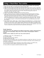
Page 25: ...ing clothing over the transmitter strap doesn t affect performance 6 Your workout must be within range distance between transmitter receiver to achieve a strong steady signal The length of range may vary somewhat but generally stay close enough to the console to maintain good strong reliable readings Wearing the transmitter immediately against bare skin assures you of proper operation If you wish ...

Page 26: ...RC percent The default is 70 you may select 60 or 80 also Adjust the level and then press enter 6 You are now asked to select the Target heart rate Level This is the heart rate level you will experience during the program Adjust the level and then press enter 7 Now you are finished editing the settings and can begin your workout by pressing the Start key You can also go back and modify your settin...

Page 27: ...console software The console has built in maintenance diagnostic software The software will allow you to change the console settings from English to Metric and turn off the beeping of the speaker when a key is pressed for example To enter the Maintenance menu may be called Engineering mode depending on version press and hold down the Start Stop and Enter keys Keep holding the keys down for about 5...

Page 28: ...re beyond the service call reimbursement period for elliptical not requiring component replacement or elliptical not in ordinary household use 3 Damages caused by services performed by persons other than authorized Spirit service companies use of parts other than original Spirit parts or external causes such as alterations modifications abuse misuse accident improper maintenance inadequate power s...

Reviews: