background image

                                                                                                                                            EL255 Elliptical


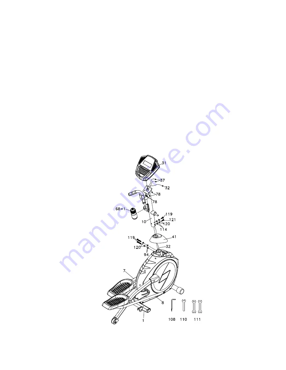
STEP 1: CONSOLE MAST ASSEMBLY


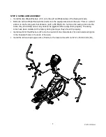
  Locate the Console Mast (10) and Console Mast Cover (41) and slide the Cover onto the Mast as 

far as it will go. Make sure the Console Mast Cover is facing the correct way. 

  At the top opening of the Main Frame (1) there is a Computer Cable (32) attached to a guiding 

wire. Unravel the wire and feed the Computer Cable into the bottom of the Console Mast tube 
and out of the top opening.   

  Install the Console Mast (10) into the receiving bracket on the top of the Main Frame. Pull slightly 

on the computer cable at the top of the mast while installing, this will ensure the cable does not 
get pinched and shorted during mast assembly.   

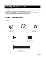
  Install 

two 

3/8" Split Washer

s

 (120) and 

two

 3/8” Curved Washer

s

 (114) onto one of the 3/8" x 3" 

Hex Head Bolt (119) and 

one of the 3/8" x 3/4" Hex Head Bolt (121)

 install through the front of the 

Console Mast; just hand tighten for now. Install two 3/8” Flat Washers (94) and two 3/8" Split 
Washers (120) onto two 3/8" x 3" Hex Head Bolts (119). Install them through the left side of the 
receiving bracket into the Console Mast. Now tighten all 3 bolts as tight as possible and snap the 
console mast cover into place.   

  There are three connectors at the top opening of the Console Mast; two Hand pulse wires (37) 

and one Computer Cable (32). Connect these to the mating connectors on the back of the 
Console Assembly (31). Store the excess wiring back into the Console Mast (10) as you carefully 
install the Console Assembly (31) onto the mounting plate of Console Mast. Secure the console 
with four M5 Phillips Head Screws (78). 


Summary of Contents for Esprit EL255

Page 1: ...ESP0021 PLEASE CAREFULLY READ THIS ENTIRE MANUAL BEFORE OPERATING YOUR NEW ELLIPTICAL Z100 Z300 Z500 Z700 OWNER S MANUAL...

Page 2: ...Instructions 3 Important Electrical Information 4 Important Operation Instructions 4 Assembly Instructions 5 Features 12 Operation of Your New Elliptical 13 Maintenance 18 Parts list and Explode Drawi...

Page 3: ...at this time to record the name of the dealer and the date of purchase below to make any future needed contact easy We appreciate your support and we will always remember that you are the reason that...

Page 4: ...tered Sparks from the motor may ignite a highly gaseous environment Never drop or insert any object into any openings Do not use outdoors To disconnect turn all controls to the off position then remov...

Page 5: ...from the computer Understand that changes in resistance do not occur immediately Set your desired level on the computer console and release the adjustment key The computer will obey the command gradua...

Page 6: ...Locate the hardware package The hardware is separated into steps Remove the tools first Remove the hardware for each step as needed to avoid confusion ASSEMBLY PACK CHECK LIST Step 1 Assembly Instruc...

Page 7: ...cs 101 17mm Wave Washer 2pcs 75 5 16 x 15mm Button Head Socket Bolt 6pcs 71 5 16 x 32mm Hex Head Bolt 2 pcs 98 5 16 x 20mm Flat Washer 2pcs 105 5 16 Nylon Nut 2 pcs 89 3 8 Nylon Nut 2 pcs 94 3 8 x 19m...

Page 8: ...iptical 7 Step 4 Tools 84 3 5mm x 12mm Sheet Metal Screw 8pcs 79 M5 x 15mm Phillips Head Screw 12pcs 108 Combination M5 Allen Wrench Phillips Head Screw Driver 1 pc 110 12mm Wrench 1pc 111 13 14mm Wre...

Page 9: ...wo 3 8 Split Washers 120 and two 3 8 Curved Washers 114 onto one of the 3 8 x 3 Hex Head Bolt 119 and one of the 3 8 x 3 4 Hex Head Bolt 121 install through the front of the Console Mast just hand tig...

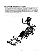
Page 10: ...Left or R Right Do not force the swing arms onto the axles they should slip on but may need to be jiggled a little to align them properly The swing arms have been installed at the factory during test...

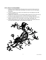
Page 11: ...ly The rod end bearing should be positioned to the inside of the swing arm brackets Install two 5 16 Hex Head Bolts 71 through the left and right swing arm brackets and the rod end and secure with 5 1...

Page 12: ...th four M5 Phillips Head Screws 79 3 Install the Front Swing Arm Covers 54 56 and Rear Swing Arm Covers 55 57 over the Swing Arm axle connections with six 3 5x12mm Self Tapping Screws 84 4 Install the...

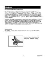
Page 13: ...ustrial Rehabilitation Center in Jonesboro Arkansas Together we identified the inherent problem in elliptical designs and developed solutions to solve the problems What we found is that when you use a...

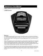
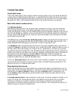
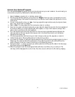
Page 14: ...ll turn on When the lights go off the dot matrix display will show a software version i e VER 1 0 and the message window will display an odometer reading The odometer reading displays how many hours t...

Page 15: ...nk answer the phone or any of the many things that could interrupt your workout this is a great feature To resume your workout during Pause just press the Start key If the Stop Reset button is pressed...

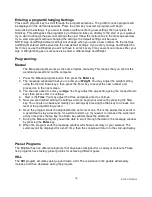
Page 16: ...t You may adjust the weight setting using the Up and Down keys then press the Enter key to accept the new number and proceed on to the next screen 3 You are now asked to enter your Age You may adjust...

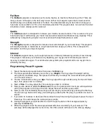
Page 17: ...y to replenish oxygen Your cardio vascular system gets programmed to use oxygen more efficiently this way Programming Preset Programs 1 Select the desired program button then press the Enter key 2 The...

Page 18: ...on t want to change then press enter to continue to the next segment 6 The next segment will show the same level as the previously adjusted segment Repeat the same process as the last segment then pre...

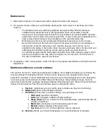
Page 19: ...lint free cloth You only need a thin coat of lubrication wipe off any excess 3 If squeaks or other noises persist check that the unit is properly leveled before calling the service department Maintena...

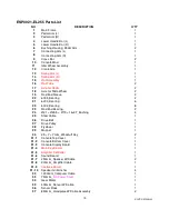
Page 20: ...eve 3 20 6005_Bearing 2 21 6203_Bearing 6 22 6003_Bearing 8 23 Rod End Bearing 2 24 31 25 5 19 16 3T_Bushing 4 25 Steel Cable 1 26 Drive Belt 1 27 Drive Pulley 1 28 Flywheel 1 29 Magnet 1 30 25 7 7m m...

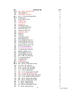
Page 21: ...5T_Round Cap 2 59 Connecting Arm Cover L 2 60 Connecting Arm Cover R 2 61 Middle Stabilizer Cover 2 62 Rear Stabilizer Cover L 1 63 Rear Stabilizer Cover R 1 64 40 80_Oval End Cap 2 65 Transportation...

Page 22: ..._Carriage Bolt 1 104 17 23 5 2T_Flat Washer 2 105 5 16 7T_Nyloc Nut 2 106 3 5 16m m_Tapping Screw 3 108 Combination M5 Allen Wrench Phillips Head Screw Driver 1 110 12m m_Wrench 1 111 13 14m m_Wrench...

Page 23: ...EL255 Elliptical 22 ESP0021 EL255 Explode Drawing...

Page 24: ...placing or repairing the product at the discretion of our authorised service centre Any enquiries relating to warranties or spare parts must first be directed to our Freecall 1800 465 070 who will the...

Page 25: ...for a major failure and for compensation for any other reasonably foreseeable loss or damage You are also entitled to have the goods repaired or replaced if the goods fail to be of acceptable quality...

Page 26: ...The sending of replacements spare parts or the cost of repair carried out by the Service Centre will be organized and covered by Boyles Fitness If collection of the item is required this will be orga...

Reviews: