


7
Step 2
:
:
:
:
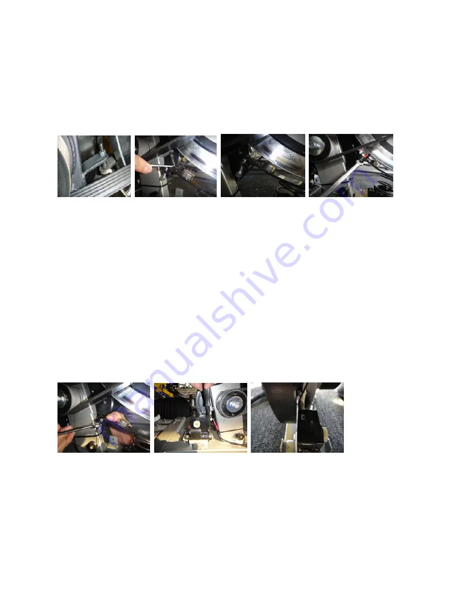
Adjust the resistance to maximum value so that the magnet housing and the screw on the stopper
touch each other, as shown in figure B-1 then adjust the screw, as shown in figure B-2, until the
distance between the magnet and the flywheel is 2mm, as shown in figure B-3. Check with control key
to see if it runs correctly. If not, adjust the screw so that the steel cable is as tight as possible, as
shown in figure B-4, and still keeps 2mm distance. Resume all parts in order when everything is OK.
Figure B-1
Figure B-2
Figure B-3
Figure B-4
Step 3
:
:
:
:
If the steel cable breaks, press the magnet housing and release the screw to separate from magnet
housing, as shown in figure C-1 and replace the cable with new one. If the cable does not break,
remove the gear motor, as shown in figure C-2 and unplug the control wire. After replacing the parts,
resume all parts in reverse order. Make sure the drive pulley does not touch the gear motor, as shown
in figure C-3.
Figure C-1
Figure C-2
Figure C-3
Summary of Contents for SE500
Page 1: ...SERVICE MANUAL SE500 ...


