background image

XG200 Elliptical

6

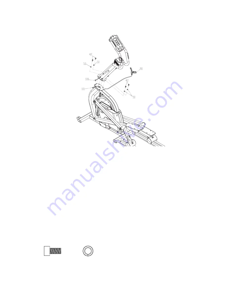
1.  The computer cable is pre-installed to the console mast and main frame so be careful not to pull 

too hard on the console mast during assembly to avoid  
damaging them. 

2.  Connect cable (

100

) to (

101

).

3.  Place the console mast onto the mating plate of the main frame; Be careful not to pinch the 

speed sensor wire between the console mast and the main frame plates during assembly.

4.  Secure the console mast in place with the four stainless steel bolts (

42

) and split washers (

50

). 

Make sure the bolts are securely tightened using the 8mm Allen wrench (

108

).

5.  Attach the hand brake lever (

90

) to the handlebars as follows:

CONSOLE MAST

1

#

42

. M10 x 20mm

Stainless Steel Bolt

(4 pcs)

#

50

. M10

Split Washer

(4 pcs)

HARDWARE


ƒ

Remove the screw that is threaded into the nut on the backside of the hand brake with the 
Phillips head screw driver (

107

)


ƒ

Place the hand brake bracket around the front of the right handlebar vertical tube, then 
insert the bolt through the back of the bracket and thread back into the nut. Tighten with the 
Phillips head screw driver (

107

)


ƒ

Loosen the two cable retainer brackets on the back of the console mast with the Phillips 
head screw driver (

107

) just enough to allow the cable to nest behind them. Retighten the 

screws after placing the cable behind them.

Summary of Contents for XG200

Page 1: ...XG200 Elliptical OWNER S MANUAL Please carefully read this entire manual before operating your new elliptical...

Page 2: ...rranted for this application Any other application voids this warranty in its entirety Product Registration Important Safety Instructions Important Electrical Instructions Important Operation Instruct...

Page 3: ...leasant as possible for many years to come If not purchased direct from Spirit the local dealership where you purchased this elliptical is your administrator for all Spirit warranty and service needs...

Page 4: ...l is not working properly call your dealer Keep the cord away from heated surfaces Do not operate where aerosol spray products are being used or where oxygen is being administered Sparks from the moto...

Page 5: ...oltage is low contact your local power company or a licensed electrician for proper testing NEVER expose this elliptical to rain or moisture This product is NOT designed for use outdoors near a pool o...

Page 6: ...ed fixed hand grips facilitate mounting and dismounting in ride recovery and controlled sprints and interval training Essential Data of Total Time RPM Speed Level Distance Pulse and total elapsed time...

Page 7: ...r any damage or missing parts If damaged parts are found or parts are missing contact your dealer immediately 3 Locate the hardware package The hardware is separated into four steps Remove the tools f...

Page 8: ...g the 8mm Allen wrench 108 5 Attach the hand brake lever 90 to the handlebars as follows CONSOLE MAST 1 42 M10 x 20mm Stainless Steel Bolt 4 pcs 50 M10 Split Washer 4 pcs HARDWARE Remove the screw tha...

Page 9: ...g arms have been previously installed at the factory and should fit properly although it is a snug fit 3 Secure the swing arms in place with the stainless steel bolts 40 flat side of washers should be...

Page 10: ...th the wrenches provided 110 111 Over tightening the hardware won t allow the wheels to rotate 2 Remove the cover on the back of the console and install the 4 C batteries 3 Snap the four end caps 67 o...

Page 11: ...ckets at the bottom of the swing arms to the pedal arms using a shoulder bolt 55 and a nut 56 on each side Tighten securely with the wrenches provided 109 116 ARM ATTACHMENTS 4 55 M10 x 20mm Shoulder...

Page 12: ...nt and rear levelers all the way in then back them out about two or three turns Level the unit using only the front and rear levelers first then adjust the middle levelers so they touch the floor Make...

Page 13: ...installed or the electrical cord is plugged into an outlet the console will power on the Time window will display an hour meter reading the Level Distance window will display an odometer reading and t...

Page 14: ...will decrease the time setting by 1 minute for each key press The time will change more rapidly when the key is held down for 2 seconds After the start key has been pressed pressing the key once will...

Page 15: ...for each pedal revolution the default is 6 If set to metric the number will be displayed in METERS the default is 1 83 To adjust the desired settings use the keys To clear odometer press and at the sa...

Page 16: ...suse accident improper maintenance inadequate power supply or acts of God 4 Products with original serial numbers that have been removed or altered 5 Products that have been sold transferred bartered...

Reviews: