Installation and Reference Manual
System Operation
44
Installation and Reference Manual v3.2/0410/6
3
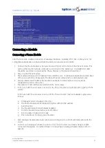
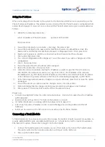
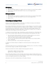
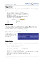
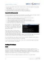
The module will request an IP address from a DHCP server. It will make 4 attempts and then back
off for a period before trying again. The back off period will extend for each failed attempt.
4
Having obtained an IP address the module broadcasts to find a Call Server to provide its
configuration and become active.
5
The SpliceCom LED will become solid when the unit is ready.
6
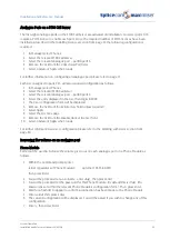
In Manager select Unassigned Modules
7
The Trunk Module will be displayed together with its MAC address
8
Select this link
9
The Module Status field will display “Available”
10
From the Module Status list box select “Member”
11
Select Update or Apply when ready
12
This unit will now be listed under Modules
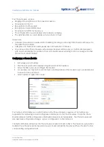
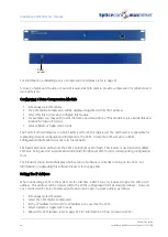
Configuring a Trunk Module
1
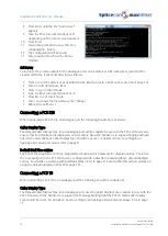
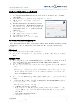
In Manager select Modules
2
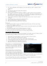
The Trunk Module (SpliceGateway) will be displayed together with its MAC address
3
Select this link to view and configure this module.
4
For example, you may wish to edit the Name and Description of this module to give an identity and
location for future reference.
5
Select Update or Apply when ready
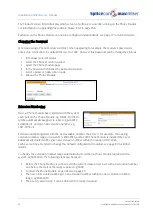
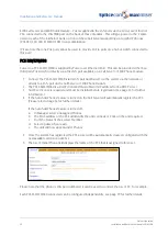
The Call Server field indicates to which Call Server the Trunk Module is registered. The Call Server is
responsible for replicating relevant configuration information to the Trunk Module. In turn the Trunk
Module will store in RAM configuration information relevant to its functionality.
The Flash LED button will instruct the Trunk Module’s SpliceCom LED to flash. This feature is useful when
multiple Trunk Modules are being used on a system and will identify the physical Trunk Module from its
corresponding configuration form.
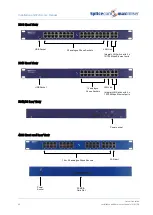
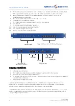
Power socket
Power socket for
Power over Ethernet PSU
4 ISDN BRI
1 ISDN PRI
Input Triggers
Relay sockets
IP WAN interface
Integral LAN Switch with 8 x 10/100 Mbps Ethernet ports
LED status lights

