9
ASSEMBLY, SETUP AND MAINTENANCE
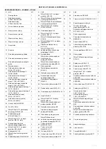
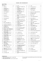
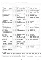
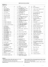
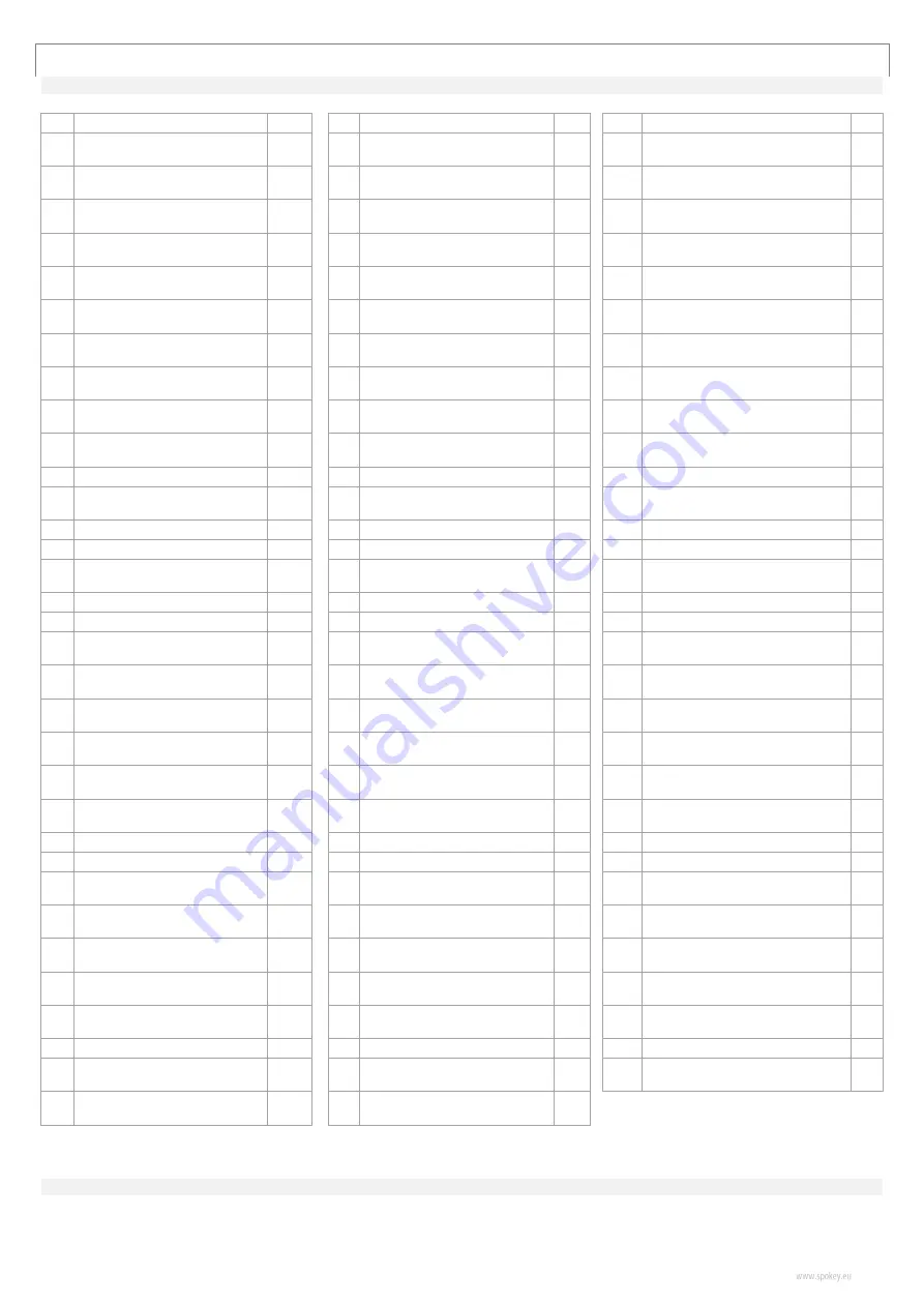
LIST OF PARTS
Diagram
– p. 50
NO. NAME
qty
NO. NAME
qty
NO. NAME
qty
1
Main frame
1
35
Allen C.K.S. full thread screw
M10×20
4
69
Belt pulley Φ308×22
1
2
Front stabilizer
PT50×100×t1.5×600
1
36
Philips pan head full thread
screw M4×12
14
70
Crank axle sleeve 2
Φ25×Φ20.1×10.2
1
3
Rear stabilizer
PT50×100×t1.5×700
1
37
Philips pan head full thread
screw M4×10
4
71
Fixed magnet set
1
4
Upper Upright post
1
38
Allen C.K.S. hollow screw
Φ10×45×M6×20
2
72
Magnetic control fixed axle Φ12×50 1
5
Body arm(L)
1
39
Flat washer Φ6
2
73
Brake tension spring
Φ11.5×Φ1.2×13
1
6
Body arm(R)
1
40
Allen C.K.S. full thread screw
M6×15
6
74
Magnet motor
1
7
Pedal supporter(L)
1
41
Philips C.K.S. self-tapping screw
ST4×16
14
75
Double flywheel Φ280/9KG
1
8
Pedal supporter(R)
1
42
Philips C.K.S. full head screw
M5×10
4
76
Motor belt 540PJ6
1
9
Handlebars
1
43
Disc plastic buckle Φ12.4×13
12
77
Upright post decoration strip
102×57×8
1
10
Console
1
44
Philips C.K.S. end-cutting self-
tappng screw ST4×10
12
78
Plastic cover Φ42.5×30
2
11
Motor communication wire
1
45 Crank iron
2
79
Handle pulse
2
12
Console communication wire
1
46
Hex half thread screw
M10×55×20
2
80
Philips C.K.S. self-tapping screw
ST4×20
2
13
Handle pulse connection wire
2
47
Hex half thread screw M4×12
2
81
Pipe plug Φ28×t1.5
2
14
Console outset
2
48
Flat key 5×5×15
2
82
Foam grip Φ32×t3.0×480
2
15
Upright post cover
339.2×107.4×154.3
1
49
Allen full thread screw M6×15
2
83
Circlip for shaft Φ12
2
16
Body Arm cover 2 160.8×103×56 2
50
Flat washer Φ8×Φ30×t3.0
2
84
Pedal(L) 406×187×74
1
17
Body Arm cover 1 160.8×103×45 2
51 Fixed idler
1
85
Pedal(R) 406×187×74
1
18
Front pedal supporter cover 1
125.1×36.7×89.4
2
55
Tension pulley Φ38×22
1
88
Deep groove ball bearing 6200-2RS 4
19
Front pedal supporter cover 2
125.1×39.7×89.4
2
56
Circlip shaft Φ10
1
89
Foam grip Φ36×t3.0×720
2
20
Rear pedal supporter cover 1
107.7×103×34.5
2
57
End cap 45×90×t1.5
4
90
Pipe plug Φ32×t1.5
2
21
Rear pedal supporter cover 2
107.7×103×37.5
2
58
Feet pad Φ49×22×M10×26
4
91
Motor cover(L) 1291.1×72×616.2
1
22
Handlebar cover(L)
209.1×147.5×57.5
1
59
Wheels Φ55×25.8
2
92
Motor cover(R) 1291.1×75.9×616.2 1
23
Handlebar cover(R)
209.1×147.5×60.5
1
60
Allen C.K.S. hollow screw
Φ8×33×M6×15
2
93
Philips C.K.S. Self-tapping screw
ST4×25
5
24
Bottle holder Φ93×150
1
61
Hex full thread screw M5×60
1
94
Circlip for holes Φ40
2
25
Axle Φ17×339.5
1
62 Hex nut M5
2
95
Self-aligning ball bearing 2203-2RS 2
26
Allen C.K.S. half thread screw
M10×60×20
4
63
Deep groove ball bearing 6004-
2RS
2
96
Hex full thread screw M8×120
1
28
Curved washer
Φ10.5×R128×t1.5
5
64 Fixed magnetic induction
1
97
Power communication wire
1
29
Allen C.K.S. full thread screw
M8×20 -left
13
65
Philips washer head end-cuttin
self-
tapping screw ST4×12
1
98
Magnetic sensor
1
32
Hex self-locking nut M10
3
66
Crank axle sleeve 1
Φ25×Φ20.1×4.6
1
99
Power adapter
1
33
Allen C.K.S. full thread screw
M10×55×20
1
67
Crank axle sleeve 3
Φ40×Φ20.1×7.7
1
100 Brake line
1
52
Idler connecting shaft Φ15×30
1
68
Crank axle Φ20×115
1
101
Disc Φ466.6×24.1
2
53
Hex nut M8
2
86
Allen C.K.S. full thread screw
M6×12
8
102
Waved spring washer Φ17
2
54
Hex locking nut M8
7
87
Deep groove ball bearing 6003-
2RS
4
PREPARATIONS
1. Before assembly make sure there is enough space.
2. Use the recommended tools.
3. Before assembly check if there are all the parts in the box.
It is recommended that product should be assembled by at least two people
to avoid injuries.
.
Summary of Contents for 920872
Page 2: ...1 ...
Page 51: ...50 1 SCHEMAT DIAGRAM СХЕМА SCHÉMA SCHEMA SHĒMA SCHEMA ...
Page 53: ...52 1 KROK STEP ШАГ ŽINGSNIS SOLIS SCHRITT 2 KROK STEP ШАГ ŽINGSNIS SOLIS SCHRITT 26 28 26 28 ...
Page 54: ...53 3 KROK STEP ШАГ ŽINGSNIS SOLIS SCHRITT 26 28 32 29 33 35 ...
Page 55: ...54 4 KROK STEP ШАГ ŽINGSNIS SOLIS SCHRITT 29 36 ...
Page 57: ...56 7 KROK STEP ШАГ ŽINGSNIS SOLIS SCHRITT 42 36 ...
Page 59: ...58 1 2 3 4 5 6 7 8 9 ...
Page 60: ...59 2 3 4 5 ...


