10
INSTALLATION INSTRUCTIONS
(Drawings
– p. 5
2
)
STEP 1
Attach the front stabilizer (2) to the main frame (1) with curved
washer(28), springwasher(27) and Allen C.K.S. half thread screw(26).
STEP 2
Attach the rear stabilizer (3) to the main frame (1) with curved
washer(28), spring washer(27) and Allen C.K.S. half thread screw(26).
STEP 3
1.Take upright post cover(15) off from the main frame(1) and cover it on
the upper upright post.(4)
2.Connect motor communication wire(11) and console communication
wire.(12)
3.Attach upper upright post(4) to the main frame(1) with flat washer(31),
spring washer(30), Allen C.K.S. full thread screw(29) and flat washer(34),
spring washer(27), Allen C.K.S. half thread screw(35) and Allen C.K.S. half
thread screw(33), curved washer(28), Hex self-locking nut(32).
4.Attach upright post cover(15) to the main frame(1) and install the
Axle(25).
Tip:Do not fully tighten the Bolt yet. Make sure that all screws are in the
hexagonal hole
STEP 4
1. Assemble the waved spring washers (102) to the left and right Axle (25).
then attach left body arm(5) and right body arm(6) to the left Axle(25) and
right Axle(25) with flat washer(31)and Allen C.K.S. full thread screw(29).
2.Attach arm cover(16/17) to the left body arm(5) with Philips pan head full
thread screw(36).
3.Repeat the last step to attach cover(16/17) to the right body arm(6).
STEP 5
1.Attach the axle sleeve of left rear pedal supporter(7) to the axle of main
frame(1) with Flat washer (31) and Allen C.K.S. full thread screw(29).
2.Attach the axle sleeve of left front pedal supporter(7) to left body arm(5)
with Allen C.K.S. hollow screw(38), flat washer(39) and Allen C.K.S. full
thread screw(40).
3.Attach the rear cover of pedal supporter(20/21) to left pedal supporter(7)
with Philips pan head full thread screw(36). Attach the front cover of pedal
supporter(18/19) to left pedal supporter(7) with Philips pan head full
thread screw(37) and Philips C.K.S. self-tapping screw(41).
4.Install right pedal supporter(8) with the same way.
STEP 6
1.Through handle pulse connection wire(13) out of the upper upright
post(4). Attach handlebars(9) to upright post(4) with flat washer(31), spring
washer(30) and Philips pan head full thread screw(36).
2.Attach bottle holder(24) to upper upright post(4) with Philips pan head full
thread screw(36).
STEP 7
1.Connect console communication wire(12) with the interface of back
console. Connect handle pulse communication wire (13) with console
outset(14).
2.Attach console(10) to upper upright post(4) with Philips C.K.S. self-
tapping screw(41).
3.Through left handlebar cover(22) and right handlebar cover(23) out of the
handlebar(9). Attach them to the upper upright post(4) with Philips pan
head full thread screw(36).
Levelling, moving the device
Before you start exercising, it is recommended to verify whether the bike is
positioned correctly. Level the equipment with the knobs of the front
stabilizer. To transport the device, raise it carefully on its front wheels
(Figure
– p. 57) and move to another place, holding it on both sides.
Resistance adjustment
The function of intensity regulation allows you to change pedal resistance.
High resistance requires a greater effort during pedalling while a low one
reduces the needed effort. Resistive force can be regulated by means of
the computer. To achieve a satisfying result, intensity should be adjusted
during workout, by means of knob UP (+) and DOWN (-).Available
resistance levels: from 1 to 32. The load system is independent of speed.
MAINTENANCE
Prior to each use of the bicycle, make sure that all the bolts, nuts and
knobs are tightly fitting.
Aggressive cleaning products must not be used to clean the device. Use
a soft, damp cloth to remove dirt and dust. Clean sweat traces since
acidic pH may damage the upholstery.
The device should be kept in a dry place in order to protect it against
dampness and corrosion.
Should the computer work incorrectly, make sure that all the cables are
connected appropriately, especially the upper cable with the computer. If
the computer still does not work, make sure that batteries have been put
in appropriately and that they are not worn-out. If the readout on the
display screen is not legible or some elements are invisible, replace
batteries immediately.
In case of no resistance adjustment, make sure that the upper sensor
cable is well connected with the lower cable.
CAUTION: Due to the protection of the natural environment, worn-out
batteries, power adapters, motors etc. should not be disposed with
household wastes. Worn-out batteries, power adapters, motors etc. should
be taken to a point that will utilise them in agreement with the enforceable
law on environmental protection. It is recommended to check the power
cord and the plug periodically. Never pull the cord. In case of damage, the
device should not be used. Never repair the device on your own. Repairs
should be made by a q
ualified SPOKEY’s company employee.
COUNTER INSTRUCTIONS
POWER SUPPLY
230V/50Hz or 60Hz Output: 9V AC/0.5A
After 4 minutes, the meter enters the energy saving mode. All settings
and data are kept until restarting the meter. In case the screen does not
start, disconnect power supply and wait for 15 seconds.
Switching on (picture 1, p. 58)
Connect the power supply, the computer will be switched on and will display
all the segments on the LCD screen for 2 seconds.
After 4 minutes without pedalling or input impulses, the console will go to
the energy saving mode. Press any key to wake up the console.
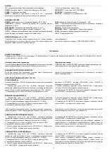
BUTONS
UP
- Increasing resistance / Increasing the entered value
DOWN
- Decreasing resistance / Decreasing the entered value
ENTER
- Confirming the selection
RESET
- Enter and hold for 2 seconds
– the computer will restart and return
to the user’s mode. Press the reset button to return to the main menu.
START/ STOP
- Start or Stop of WORKOUT
RecoveRY
- Testing the pulse
BODY FAT
- Percentage test of the fat tissue and the BMI
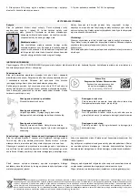
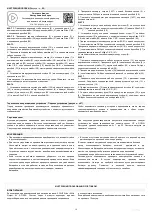
Watch the movie:
Assembly instruction.
Scan the presented code
or type the address into your web browser:
http://bit.ly/spokey-vigo2
Summary of Contents for 920872
Page 2: ...1 ...
Page 51: ...50 1 SCHEMAT DIAGRAM СХЕМА SCHÉMA SCHEMA SHĒMA SCHEMA ...
Page 53: ...52 1 KROK STEP ШАГ ŽINGSNIS SOLIS SCHRITT 2 KROK STEP ШАГ ŽINGSNIS SOLIS SCHRITT 26 28 26 28 ...
Page 54: ...53 3 KROK STEP ШАГ ŽINGSNIS SOLIS SCHRITT 26 28 32 29 33 35 ...
Page 55: ...54 4 KROK STEP ШАГ ŽINGSNIS SOLIS SCHRITT 29 36 ...
Page 57: ...56 7 KROK STEP ШАГ ŽINGSNIS SOLIS SCHRITT 42 36 ...
Page 59: ...58 1 2 3 4 5 6 7 8 9 ...
Page 60: ...59 2 3 4 5 ...


