
- 7 -
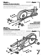
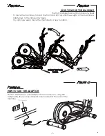
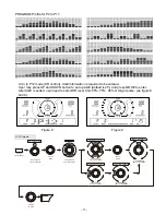
HOW TO MOVE THE MACHINE
The front stabilizer has built-in transport wheels.
To move the machine, stand at the front and lift it up until the weight of the machine is
transferred to the transport wheels.
You can now easily move the machine to a new location.
(
+)74'
(
+)74'
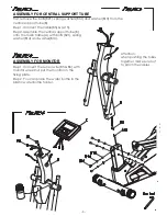
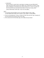
(E3)Adaptor
Position Machine on consideration for convenience, using the
adaptor(N), there is one adaptor hole located at the rear of the
machine.
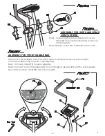
HOW TO USE THE ADAPTOR
Summary of Contents for E7000P PLUS
Page 1: ...E7000P PLUS ...
Page 9: ... 8 ...


