background image

-7-

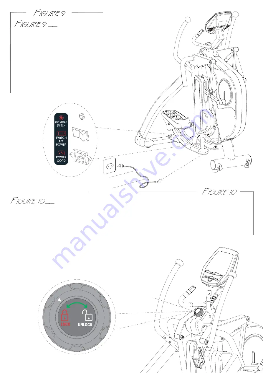
POWER CORD ASSEMBLY

Attach the power cord jacket into the power socket on 

the main frame before plugging the power cord plug into 

the wall outlet. 

Turn the AC power switch on. 

Flip the ON/OFF switch to the ON position. 

"0" sign is for OFF; "I" sign is for ON.

Note: The Overload switch is for device over loading 

protection. Overload switch will pop-up when the 

machine is electrically over loaded. Turn off the AC 

power switch and turn it back on to restart 

the machine.

FOR YOUR SAFETY, this machine is equipped with a pedal locking feature. The

pedals can be manually disabled so that it cannot be moved accidently. Turn the knob left 

or right one click until you see the arrow point to the “LOCK OR UNLOCK” symbol. While the 

machine is in idle; NEVER in motion, turn the knob (A3) to “LOCK” to disable the pedals or turn 

the knob to “UNLOCK” to release the pedals. The machine should always be at the “LOCK” 

position when NOT in use. It would prevent the children or user from being hurt.   

WARNING: FOR YOUR SAFETY, never lock the pedal locking feature 

                    while the machine is in motion, only when it is at a full 

                    complete stop it is safe to move the knob.


Pedal Locking Feature

A3

Summary of Contents for RO 700

Page 1: ......

Page 2: ...e the top polyfoam pieces 1 2 and finish up packing the console console supporting tube central supporting tube pedal supporting tube and hardware bag leaving the main frame A and bottom polyfoam piec...

Page 3: ...g tube L B2 Pedal supporting tube R Console Console supporting tube Bot r E1 Handle bar L E2 Handle bar R F1 Central supporting tube C2 Side connecting tube R C1 Side connecting tube L F2 Iron bracket...

Page 4: ...2 465 56 J6 Screw M8X20 J4 Screw M8X55 J10 Screw M12X109 J7 Screw M12X73 J13 Screw M8X16 J9 Nut M12 J2 Screw M4X16 J3 Screw M4X6 J14 Screw M5 J8 Washer M12 J5 Washer M8 4m m 19 6m m 2 5m m 2...

Page 5: ...ew J2 Step 2 Follow the step 2 1 to 2 4 to assemble the side tube cover sets 2 1 Connect the covers R1 R2 onto the right side connecting tube C2 2 2 Connect the cover R3 onto the tube C2 2 3 Connect t...

Page 6: ...NNECTING TUBE ASSEMBLY USE TOOL 6m m RIGHT SIDE CONNECTING TUBE ASSEMBLY Step 1 As shown in Views A B Assemble the right side connecting tube C2 assembly to the machine Step 2 As shown in View A Assem...

Page 7: ...eat the previous same steps for the left pedal supporting tube B1 assembly VIEW C VIEW D A J8 J9 J7 B2 J9 J10 B5 J8 VIEW E USE TOOL 6m m 19 HANDLE BAR ASSEMBLY Step 1 Remove the six preinstalled screw...

Page 8: ...iver CONSOLE SUPPORTING TUBE AND BOTTLE HOLDER ASSEMBLY Step 1 Connect wires D1 D2 from the console supporting tube D to wires A1 A2 from the main frame A Step 2 Slide the console supporting tube D on...

Page 9: ...ETY this machine is equipped with a pedal locking feature The pedals can be manually disabled so that it cannot be moved accidently Turn the knob left or right one click until you see the arrow point...

Page 10: ...levelers on the bottom rear of supporting tubes to stabilize the machine if needed WARNING Never attempt to lift the machine by yourself ask for additional help if needed and never attempt to lift th...

Page 11: ...normal jog run stride Next reason why a user may want to adjust the stride length during a workout is to work different muscle groups a shorter stride length will work different muscles in your legs a...

Page 12: ...count down from 0 60 P1 Swift to program profile 1 P2 Swift to program profile 2 P3 Swift to program profile 3 P4 Swift to program profile 4 P5 Swift to program profile 5 P6 Swift to program profile 6...

Page 13: ...t training time from 00 00 to 99 00 Press MODE to confirm setting DISTANCE is blinking You may press UP or DOWN button to set up target distance from 0 00 99 59 Press MODE to confirm setting CALORIES...

Page 14: ...n and press MODE to confirm There are 16 columns for the profile TIME is blinking You may press UP or DOWN button to set up target training time from 00 00 to 99 00 Press MODE to confirm setting DISTA...

Page 15: ...confirm setting DISTANCE is blinking You may press UP or DOWN button to set up target distance from 0 00 99 59 Press MODE to confirm setting CALORIES is blinking You may press UP or DOWN button to se...

Reviews: