background image

22

STEP 13  

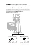
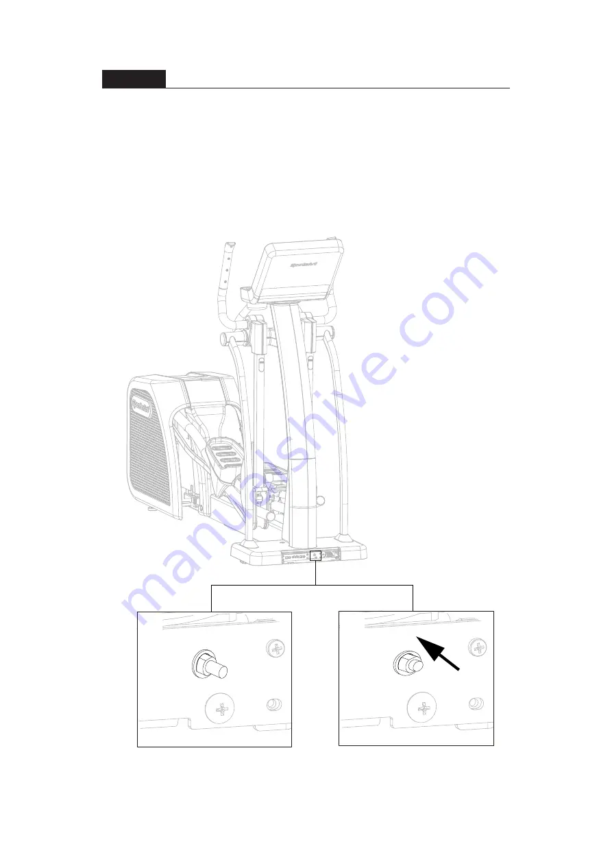
 Power Supply Protection(Circuit Breaker)

When current is overloaded, the Circuit Breaker will work to protect the
machine from damage. In the following picture (a) you will find a round button
(D), which is the device of circuit breaker, it will pop up when current is
overloaded, please turn off the machine in this situation. After the maintenance
personnel find and solve the problems, press the button as shown in picture
(b), then restart the machine to get back to exercising.
The picture below is for your reference.

D

(a)

(b)

Summary of Contents for G876

Page 1: ...unctions Guide 21 STEP 13 Power Supply Protection Circuit Breaker 22 6 UNDERSTAND THE G876 DISPLAY 23 DISPLAY Overview 23 DISPLAY Console Panel 23 DISPLAY Windows Display 25 DISPLAY Specifications 26...

Page 2: ...AINTENANCE 46 MAINTENANCE Safety Precautions 46 MAINTENANCE Error Messages 47 MAINTENANCE Lubrication 49 MAINTENANCE Lubrication Procedure 49 MAINTENANCE Cleaning the Glide Rails 50 MAINTENANCE Schedu...

Page 3: ...s and designed for years of reliable performance this product was made for full commercial use Before this product is assembled or operated we recommend that you familiarize yourself with this manual...

Page 4: ...Do not use accessories or parts that are not specifically recommended by the manufacturer SportsArt Such parts might cause injuries or cause the unit to fail and void the warranty We are not responsib...

Page 5: ...or abnormal sensation STOP YOUR WORKOUT and consult your physician immediately Work within your recommended exer cise level DO NOT work to exhaustion Before beginning any exercise program you should c...

Page 6: ...l as shown otherwise you can also stick it on a place where is clear and obvious please use the French version label in French Speaking areas in North America and the label will not be included in the...

Page 7: ...8 Right roller cover 1 A2 Right pedal 1 A9 Left joint cover 1 A3 Left pedal 1 A10 Right joint cover 1 A4 Left support tube 1 A11 Pedestal cover B 1 A5 Right support tube 1 A12 Pedestal cover E 1 A6 Co...

Page 8: ...1 14mm 15mm Screwdriver handle 1 black Screwdriver bit 1 Flat and Phillips Pre Installed Hardware No Name Specification Notes 21 Phillips screw M4 P0 7 L8 22 Inner hex screw 5 16 L2 1 4 half Flat was...

Page 9: ...9 5 ASSEMBLE THE PRODUCT STEP 1 Install the Main Frame a Unfold the main frame A1 and make it stand b Secure screws 10 to the main frame...

Page 10: ...g parts a Remove screws 21 from the pedal arm attached to the main frame A1 b Slip the glide rail into area A then gently place the pedal carriage on the glide rail support c Connect the guide roller...

Page 11: ...lace on the bushing and use the screw 22 to secure it into place Then press the stride adjustment linkage cover 11 into place Note Carry out the same procedure on the right side of the product as well...

Page 12: ...Follow steps a through b to install the support tubes a Remove support tube screws 23 24 from the main frame A1 b Insert left and right support tubes A4 A5 into the axle area and base and loosely secu...

Page 13: ...dlebar A13 Insert the stationary handlebar A13 into place on the support tubes and secure them with screw 25 b Remove screws 26 from the sides of the left and right support tubes A4 A5 Snap joint cove...

Page 14: ...r 28 upward and remove it b Connect the cables of the console to the pedestal and then secure the console into place with screw 29 c Connect the cables of the main frame to the cables of the console A...

Page 15: ...gle as shown below and then press it into place Repeat the same step with the left pedal c Secure the lower half of the right pedal with screw 31 and be sure to se cure the screws in the rectangular f...

Page 16: ...l cover onto the mount by a downward push Once it is locked completely secure it with screw 27 and then secure the pedestal cover E A12 with screw 30 b Insert the pedestal cover B A11 to the base fram...

Page 17: ...sh the product into location for use Be careful to avoid pinching fingers when setting the product down b Two people Have one person grip the front base of the product while the other person grips the...

Page 18: ...lliptical trainer must sit level on a flat floor If necessary adjust the levelers by following instructions a through c below a Loosen the leveler nut b Rotate the leveler foot downward so it firmly t...

Page 19: ...e the pre installed screws 33 from the machine prior to assembly 2 Push the plug cover of the power cord toward and against the plug 3 Plug in the power cord A14 and secure it with the screws 33 The p...

Page 20: ...This product has moving parts that could be a danger to people and animals During use do not put hands or other objects into the stride adjustment slot the rear cover opening or other areas in which s...

Page 21: ...21 STEP 12 Essential Functions Guide LENGTH Adjust the distance between two successive placements of the same foot RESISTANCE Adjust the weight or force you need to place on the pedals to push them...

Page 22: ...ng picture a you will find a round button D which is the device of circuit breaker it will pop up when current is overloaded pleaseturnoffthemachineinthissituation Afterthemaintenance personnel find a...

Page 23: ...1 LCD Window Display the data of RESISTANCE TIME DISTANCE HEART RATE CALORIES Instant Watt To GRID 2 GOAL Select Area Options TIME DISTANCE CALORIES Watt hour To GRID 3 STRIDE Press this key to change...

Page 24: ...ilable if you purchase SA WELL 10 RESISTANCE Press RESISTANCE to set the resis tance 11 Numeric Keypad Press these keys to directly input numeric values 12 CHANGE DIS PLAY Press this key to switch the...

Page 25: ...TOTAL STRIDES Display your total strides 5 RESISTANCE Display your current resistance STRIDE LENGTH Display your current stride length 6 he Instant Watt to GRID during exercise 7 TARGET GRID Wh Displa...

Page 26: ...TH 17 29 inch 450 730mm CAL HR 0 9999 K CAL TIME 0 00 99 59 100 9999 DISTANCE 0 00 9999 Mile KM display maximum of 2 decimal places CALORIES 0 9999 K CAL SPM 5 150 HEART RATE 35 255 bpm Instant Watt T...

Page 27: ...UCT OPERATION Safe Operating Area a Safety clearance required as shown below Do not allow people to be near this area when operating b Noise emission under load is higher than without load 600mm 23 6...

Page 28: ...ce your feet on floor and then hold the handles to steady self while stepping on the pedals as shown below b Wait until pedals come to a complete stop and then hold onto handles for stability while ca...

Page 29: ...r user is shown below b Over exercising or improper workout form may result in serious injury c User can hold onto handles for stability when getting on or getting off from the right left side of the...

Page 30: ...elliptical trainer measures your calories burned based on weight target heart rate based on age total time and total distance based on your personal information that you have entered 1 PROGRAM GOAL S...

Page 31: ...CALORIES button light will stay on and then proceed to calories settings The range is 100 9999 kCal with the default of 100 kCal Press WATT HOUR TO GRID and select the Power Gen eration as your goal...

Page 32: ...corner of the display MANUAL The general mode The resistance can be adjusted according to your own preference INTERVAL Regularly alternate between high intensity and low intensity exercises 1 The prog...

Page 33: ...ress the ENTER key to confirm your choice During program setting you may press QUICK START to start the program right away The maximum stride length can be adjusted during exercising by pressing STRID...

Page 34: ...AGE 0 80 2 If you choose CUSTOM HR the target heart rate value will need to be set first The range is 84 200 bpm with the default of 120 bpm 3 During exercise if the machine cannot read your heartbea...

Page 35: ...lating and keep the current value and the window will show the message PAUSED and PRESS QUICK START TO RESUME in cycles 2 Without any movements for 20 seconds while paused the window will return to st...

Page 36: ...the buttons for 30 seconds and the window will display and continue to flash To restart the machine please step on the pedal or press any button to return to start screen OPERATION Energy Smart Functi...

Page 37: ...rogram press RESISTANCE or STRIDE to view each program version then press ENTER and go to the next step Program Version Items a CTL SA_6 xx The program version of the control board b DRV MI xx yyyy Th...

Page 38: ...ing The window will show the message of LIMIT press RESISTANCE key or numeric keypad to set the time then press ENTER to confirm and go to the next step If the time limit is set less than 5 minutes th...

Page 39: ...reception For best results install the product in an area free from such interference Space the product apart by at least 39 inches 100 cm to avoid having the heart rate value from one exerciser appe...

Page 40: ...st depend on your fitness level In general it is recom mended that you maintain a heart rate within your training zone for at least 15 to 20 minutes to experience the benefits of aerobic exercise Begi...

Page 41: ...se carefully note the meaning of the following warning symbols abide by their messages and thoroughly read these instructions This WARNING symbol indicates a risk of electric shock Please use ex treme...

Page 42: ...ource Chaque circuit doit tre coup avant toute intervention de d pannage Attendre 5 minutes avant de retirer le couvercle une fois toutes les sources d alimentation coup es CAUTION Perform all electr...

Page 43: ...or USA 230VAC 184 1 264 4V for EU Maximum continuous output current 2 0A for 120V for USA 1 3A for 230V for EU Normal output frequency Operating frequency range 60Hz 59 3 60 5Hz for USA 50Hz 47 4 50 1...

Page 44: ...uct power switch to OFF and unplug the power cord from the wall outlet before pulling the plug from the product If the plug is pulled while it is connecting to the power grid it might cause the electr...

Page 45: ...Eco Powr Products 2nd 3rd 4th NFB Power on Start pedaling the elliptical trainer with 40SPM or above for more than 6 seconds to turn on the unit Start operating the elliptical trainer when the display...

Page 46: ...Never spray or pour any liquid directly onto the product Doing so can damage electronic components and void the warranty Use a clean lint free towel dampened with a mixture of Simple Green all purpose...

Page 47: ...Main Code X Secondary Code Y Error message Note 1 1 System boot error 1 6 2 1 IGBT s current is overloaded DC bus Overcurrent 2 2 IGBT s temperature is too high 3 1 The AC power supply is failure or t...

Page 48: ...de The stride motor stops but other functions of the elliptical trainer still work Turn off the main power switch off the motor and its driver circuit 7 2 Right stride length error The SELECT PROGRAM...

Page 49: ...cedure is completed please follow below instruction to return the stride length to 29 730mm 1 When the power is off pedaling the elliptical to turn on the power 2 Press and hold the STOP key for 2 sec...

Page 50: ...de rails on a daily basis a Use a clean lint free cloth to wipe dust and debris off the glide rails b Test operate the product to determine where dirt might remain on the glide rails c Repeat steps a...

Page 51: ...Quarter Year Notes 1 Exterior Clean 2 Screws Inspect and secure loose parts 3 Glide rail Wipe away dirt and debris 4 Rollers Apply silicone lubricant 5 Stride motor Apply bearing grease 6 Cushion Lub...

Page 52: ...B port provides up to 5V 1A of power for charging CSAFE PORT Compatible with CSAFE Communications Specification for Fitness Equip ment Protocol To support MYE Wireless TV Audio_Channel Receiver and th...

Page 53: ...ailable for download in the App Store and Google Play 2 Use USB Flash Drive to store the workout data 3 Manage user information and workout data Visit www gosportsart com for more information about th...

Page 54: ...54 ACCESSORIES Option Continued 1 External TV Mount...

Page 55: ...Wireless TV transmission frequency in Europe is mostly 863MHZ or nomi nally 800MHZ Operation instruction Turn off unit power plug the receiver into the CSAFE port located at left of display and then...

Page 56: ...nsions L 2222 mm 87 5 W 670 mm 26 4 H 1756 mm 69 Overall Weight 185 kg 407 lbs Maximum User Weight 150 kg 330 lbs Power Requirement 100 120 V 60 Hz USA 220 240 V 50 Hz EUROPE Circuit Breaker Current R...

Page 57: ...otor Numeric Key Board HTR Board Head Phone Board USB Board Control Board EUP Board Key Board USB Board SA WELL Connection key SA WELL Option RFID Board Rocker Board HRC Board Fan Contact HTR plates A...

Page 58: ...58 APPENDIX Exploded Diagrams...

Page 59: ...59 APPENDIX Exploded Diagrams...

Page 60: ...60 APPENDIX Exploded Diagrams Continued...

Page 61: ...61 APPENDIX Disassembly a Main Frame b Lift Motor Assembly c Front Base Cover a1 c2 c1 b1 b6 c3 b2 b4 b5 b3...

Page 62: ...62 Your Authorized Distributor...

Reviews: